HJ47 welcome here?

This site may earn a commission from merchant affiliate
links, including eBay, Amazon, Skimlinks, and others.

.... had the hole in it for the accordion-like hose.....

I was looking at that hose. What does it do?

....Then I noticed another thing - the fan vanes are of two varieties, one with the blades oriented left and one tilted right. As the blower housings are shaped inside to put the vane to one side and allow space for more air to be pushed out on the other, I realized that the difference in vane direction was yet another aspect of difference between LHD and RHD vehicle.........

Very useful info for people sourcing replacement fans. (I never suspected the centrifugal-fan blades would be different.)

...I also noticed that the motor housing comes from the factory with some sort of fabric tape wrapping the housing in two seam locations. I wonder if it's some sort of special tape of which I've never heard?........

I've seen that type of tape before but only many years ago. It is certainly ideal for this application because it seems to have no "tendency-to-peel-back-at-the-ends" with age. When I cleaned up my fan assembly recently I just used a fabric-type black tape for the top seam and sealed the bottom one with paint during the painting process.

I suspect my tape will tend to "peel-back-at-the-ends" after a few years so I ran a thin black cable-tie around it just below the connection plug to at least stop the lower bit from peeling back.

Here's a link to the thread I did on "reconditioning my fan":

https://forum.ih8mud.com/40-55-series-tech/192881-gave-my-heater-fan-assy-birthday.html

....Has anyone come across a suitable pull-out fan switch with more than two speed settings?....

Sorry HJ. Can't help you here,
 
Quote:
Originally Posted by Henry James the 47th
.... had the hole in it for the accordion-like hose.....

"I was looking at that hose. What does it do?"

I'm not sure exactly. From the side of the fan motor, it emerges below the fan vane inside the housing. The fan is pushing air up and away from the base of the housing, so it would appear that the fan would also draw air up the hose, and away from the base of the motor (?). Perhaps this helps cool the motor, or remove moist air??

Ya got me.
 
......I'm not sure exactly. From the side of the fan motor, it emerges below the fan vane inside the housing. The fan is pushing air up and away from the base of the housing, so it would appear that the fan would also draw air up the hose, and away from the base of the motor (?). Perhaps this helps cool the motor, or remove moist air??

Ya got me.

Interesting.

I wonder if someone else can tell us whether this is a previous-owner modification or a factory one.
 
This is definitely a factory thing - the hose is molded specifically to fit onto the fan motor housing and the blower housing.

Oh well that's good news HJ. Nothing to worry about then. (It must be an improvement.)
 
Next item on the list: pto shaft install. I realized that one of the pillow blocks in my HJ61 3-sectional drive shaft would have to go. I cut it out, using a wrap of painter's tape to help guide my cut with the zip wheel. I learned that the drive-shaft is hollow, which made it easier to cut.
DSC09342-small.webp
DSC09343-small.webp
DSC09344-small.webp
 
Once the pillow block section was removed, I placed each shaft end in their respective yokes and slid them in to the appropriate depth. Then I marked the overlap, cut the one shaft to length, and beveled the ends in preparation for welding.
DSC09345-small.webp
DSC09346-small.webp
DSC09347-small.webp
 
Last edited:
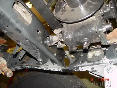
After the weld was complete, then ground off and the warmed-up iron shot with etching primer, I turned my attention to the more difficult item: the mounting bracket for the pillow bearing block. I was able to place the u-joint ahead of the bearing block and tucked up under the engine mount. It seems like a well protected position, but I couldn't be too sloppy about the positioning or the u-joint might run into the engine mount webbing. I also wanted the winch end shaft to go through it's access hole in the chassis crosspiece in a fairly centered position.. I fixed the winch into place a little more firmly, then set to work chopping up some angle iron to make the bracket. It's a little overkill on the beefiness scale, but that's the metal I had on hand.

A good discovery, and the primary one that drove the bracket design, were a pair of 6mm bolt holes on the underside of the chassis rail, in close proximity to the centerline of the pillow block. I also needed to put a large hole in the middle of the angle iron cut-out, as the two blot holes straddled a chassis rivet head.
DSC09351-small.webp
DSC09352-small.webp
DSC09353-small.webp
 
Last edited:
Here's some pics to try and show the fit of the driveshaft spline end into the yoke (pic 1), a dark one indicating the fit at the winch yoke end (pic 3), and another showing how the clearance looks between the u-joint and the frame and the engine oil pan (pic 2).

Another TICK off the list. I only need to paint the shaft and mounting bracket. That will have to wait until a little warmer weather comes along, probably a month at least. It's good to have the pto install pretty much completed, from lever on out to the winch. There is a last bit to attend to, which is the plate with two detent holes for the winch actuation lever that will attach to the upper lip of the bumper or the top of the triangular gusset. Next time.

:bounce:
DSC09363-small.webp
DSC09366-small.webp
DSC09364-small.webp
 
Last edited:
Nice work HJ.

Did you ever come across this photos from another thread on MUD?

I'm going to try any copy this set-up using an extension to the LH radiator support bracket:

PTO4.webp

PTO7.webp

:cheers:
PTO4.webp
PTO7.webp
 
No LostMarbles, that was the first I've seen of that other thread. Looks like a factory set up - is it? Is that the only pillow block on the drive shaft?

I wanted to support my drive shaft at about the midpoint, and without too much slice/dice on the 3-section driveshaft, and am satisfied with the result. I think if I placed just a single pillow block at the lower rad support, as shown in those photos, the straight run of the shaft back to the gearbox would bring it awfully close to the oil pan.

I've seen on the EPC that there were both 2 and 3-section drive shafts for the HJ47, but I have never seen the 3-section type in a 40 series.
 
Last edited:
... Looks like a factory set up - is it?.........

Well that is what I am assuming.

... Is that the only pillow block on the drive shaft?..

Yes (Based on both my set-up and the photos I've seen of this one where the photos came from.)

....I wanted to support my driveshaft at about the midpoint, and without too much slice/dice on the 3-section driveshaft, and am satisfied with the result. I think if I placed just a singel pillow block at the lower rad support, as shown in those photos, the straight run of the shaft back to the geabox would brigng it awfully close to the oil pan.........

I'm sure you're right. (I think the 3-section drive shafts were designed specifically for longer vehicles like yours.)

If I put a mid-section pillow-block on mine it would fight the movement of the engine/transmission on its rubber mounts. But the 3-section driveshaft no doubt allows you to do it successfully.

...I've seen on the EPC that there were both 2 and 3-section driveshafts fo the HJ47, but I have never seen the 3-section type in a 40 series.

Yeah. I think the short wheelbase doesn't warrent a 3-section.

:cheers:
 
Another interesting difference between your PTO set-up and mine is that mine has the forward-neutral-reverse shifting mechanism mounted on the rear of my PTO g/box but yours is mounted on the front.

:cheers:
 
"I'm sure you're right. (I think the 3-section drive shafts were designed specifically for longer vehicles like yours.)"


-- BUT, the length difference in the long wheelbase 45/47's and the shorter versions is all accounted for in the rear part of the chassis. From the engine mounts forward the long wheel base and short wheelbase trucks are identical. The three-section shaft I had came from an HJ60, which is definitely longer from the transfer to the winch.

" If I put a mid-section pillow-block on mine it would fight the movement of the engine/transmission on its rubber mounts. But the 3-section drive shaft no doubt allows you to do it successfully."

--the movement of the engine/transmission on their rubber mounts is accounted for at the points, forward and rear, where the splined driveshaft inserts into the respective yokes. It's a sliding connection, one that would easily accommodate 0.25' or more of to and fro movement of the engine and tranny, so there's no worry about the parts fighting each other. I've seen 2-section pto shafts on 40's that have a pillow block in roughly the same place as mine. The one you showed in those pictures with the very forward-mounted pillow block on the rad mount was new to me.

I've attached a picture from a 1961 Toyota publication showing some details about the pto - note the placement of the pillow block, which is the same as the one in that picture you posted.

Then a couple of pictures of the pto drive i would really like to have, with cable shift, dual output, and forward-reverse.

There are lot of variations of the pto gearboxes on LC's over the years. Some have the actuation lever at the rear, as you mentioned, and use a cable to shift instead of a rod, some have dual outputs front and rear, some have an idler gear and reversing capability, etc. There are pto drives that attach to the rear of the transfer case instead of the side.

I would like to have found the dual output for the split-case with the cable actuation and forward-reverse shifting, but those are not the most common units, only from '83 trucks from what I've been able to gather. At least the one I ended up with has very low wear-and-tear on it, so it should last a while.
1961 pto mounting details-small.webp
attachment-1.webp
attachment.webp
 
Last edited:
One thing did occur to me in regards to the factory mounted pto shaft, where the radiator support bracket has those extended mounting ears on it. That cane only be done by the factory since the mounting is riveted to the crossmember. What about the owner with a radiator mounting bracket of the regular type who wants to retrofit the pto to their truck? I'm sure the factory didn't sell the other radiator bracket as a separate item

So, is it the case that all the trucks came out of the factory with that type of radiator bracket, for the early years, and then it was changed at some later point, and the pillow block relocated?..

...or is it the case that on trucks factory-built with the pto, that those type of radiator brackets were specified in those applications only...

...and that people who wanted to retrofit the pto apparatus to their trucks without the special radiator support bracket got a different type of pto shaft from the factory - one with a different mounting?

I'm just throwing out wild guesses here, in case you couldn't tell.
 
....- BUT, the length difference in the long wheelbase 45/47's and the shorter versions is all accounted for in the rear part of the chassis........

:hhmm: Hmmmm. I had a feeling I might be talking rubbish when I made that statement about the length and indeed I was.

--the movement of the engine/transmission on their rubber mounts is accounted for at the points, forward and rear, where the splined driveshaft inserts into the respective yokes. It's a sliding connection, one that would easily accommodate 0.25' or more of to and fro movement of the engine and tranny, so there's no worry about the parts fighting each other. I've seen 2-section pto shafts on 40's that have a pillow block in roughly the same place as mine....
The more I think about it, the more I realise that it is just my problem of "not being able to get my head around it" so to speak. (And I haven't had many beers tonight either.)

...I've attached a picture from a 1961 Toyota publication showing some details about the pto - note the placement of the pillow block, which is the same as the one in that picture you posted.

Then a couple of pictures of the pto drive i would really like to have, with cable shift, dual output, and forward-reverse....

Thanks heaps for those pictures too.
I felt guilty about interupting your flow with my posts but at least I've been rewarded for doing so. (I've copied that 1961 publication for myself.)

You are FAR more knowledgeable about these PTOs than I am.

:beer::beer::beer:
 

Users who are viewing this thread

Back
Top Bottom