H42 Transmission, Tcase, eBrake Rebuild in a '76 FJ40`

This site may earn a commission from merchant affiliate
links, including eBay, Amazon, Skimlinks, and others.

7-B Continued: Counter Shaft Bearings Removal

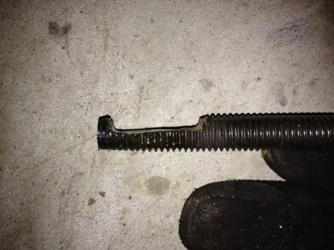
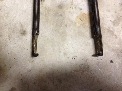
Well I had a brainstorm today and tried it. Had a puller from AutoZone tool loaner program. The claws were too big to fit but if I ground them down and inserted them sideways, they fit. I could then rotate them into place and screw them back onto the body of the puller.

image-2370475292.webp
AZ Loaner no more

image-1185802024.webp
Ground off a bit

After grinding a pair I was able to pull the countershaft bearings right off. It made the claws weaker but to enough to be defeated by these bearings.

image-3299872289.webp
Puller ready. Input side bearing

image-1808392417.webp
Socket used to turn puller

At first it pushed the output bearing out while pulling from the input side, then the input pulled out.

image-3166803508.webp
Pushed the output out a bit first

image-3199558185.webp
Then Input started coming out

image-2357063334.webp
Free at last

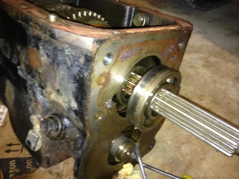
Worked on the Output bearing next.
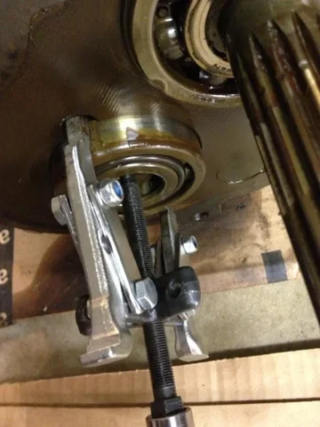
image-3199479096.webp
Output


image-3106456688.webp
Bearing in 2 parts

image-3525496326.webp
Counter Shaft Output side

Had to strap on the 3rd leg to get the input bearing all the way off the shaft once it left the case.

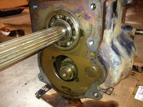
image-476175273.webp

image-2869470678.webp
image-2370475292.webp
image-1185802024.webp
image-1808392417.webp
image-3299872289.webp
image-3166803508.webp
image-3199558185.webp
image-2357063334.webp
image-3106456688.webp
image-3525496326.webp
image-476175273.webp
image-2869470678.webp
image-3199479096.webp
 
Last edited:
8. Input Shaft Removal


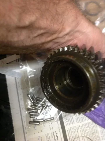
Now that the Counter shaft is out of the way, I can remove the input shaft. I just grabbed and pulled, and it came right off. The needle bearings fell out, and of course, one fell into the case. Along with every other small part possible. I'll get all those out later.


image-4283536180.webp
Input shaft coming out.

image-2307614017.webp
Needle bearings

Watch out for the synchro ring, it comes out too.

image-1572290554.webp
Synchro ring

image-3549034674.webp
Input Shaft and Synchro
image-4283536180.webp
image-1572290554.webp
image-2307614017.webp
image-3549034674.webp
 
Last edited:
Does anyone have a better description of where to place the gap tool between the synchros and gears for measuring 1st, 2nd, and 3rd gear thrust clearance?

The FSM I have is a scan in a PDF that is kind of dark. See below for a screen clip of it.

image-3329045319.webp
Measuring the Gaps

The Haynes manual talks about doing the gap measurement AFTER you take the gears off the output shaft. FSM says do it before you remove the Output shaft from the case but just isn't clear where to measure. If I could just see what to measure I could figure it out.
image-3329045319.webp
 
Dang, stuck again.

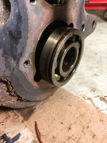
I must remove the output rear bearing. Long output shaft is in the way of my short puller, and 1st gear won't allow me to drive it from the inside.

Should I just remove the gears from the shaft then drive the bearing out?

image-3136322067.webp
Nope cannot do that. No room at the shaft end. Case is in the way.


image-3646795112.webp
Gotta remove this bearing


image-852125401.webp
I don't have a long puller.

Ok mudders - how?
image-852125401.webp
image-3136322067.webp
image-3646795112.webp
 
The rear output bearing is what convinced me not to fool with these transmissions any more. I tried using a 20 ton press at work with no success. What worked was I stuffed some styrofoam between the main shaft gears and counter shaft so that the teeth wouldn't get F'ed up, turned it over, put a piece of aluminum bar on the end of the main shaft and then hit it hard with a full two arm swing with a 10 pound sledge.

I think it I had to do it again, I would cut the inner race with a carbide or diamond burr in a pneumatic die grinder. It cuts bearing races pretty fast.

Well crap PinHead, that's not what I wanted to hear.

Did you take the retaining clip off the input-facing end of the shaft first so that the gears could slide on the shaft?

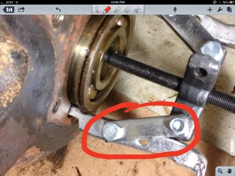
I see where I could modify my puller by replacing the short straight pieces of metal with longer ones that will allow the puller to reach the end of the shaft.

image-1512303655.webp
Replace circled connector pieces with longer ones.


image-221866306.webp
It would need to reach from the puller arm to the end of the shaft to connect to the puller body.

Or - cut it off like you said.
image-1512303655.webp
image-221866306.webp
 
10. Transmission Case Cover Disassembly

Drive the steel spring pin out of the shaft for the third-fourth shaft and fork. Drive it in whatever direction it comes out easiest. Use a drive pin that fits the pin pretty well. You don't want to expand the spring pin such that it won't come out so work carefully to get it started. I got one stuck and had to beat it hard with two different drive pins to get it out.

image-2918029360.webp
image-2736262236.webp
Remove this pin first on the short shaft

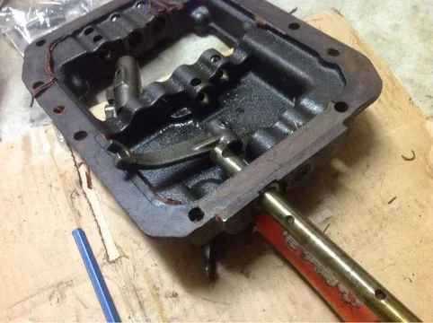
Then drive the shaft out thru the case, popping the expansion plug out.

image-2212731969.webp
image-618636660.webp
Shaft being driven out

Next, remove the two pins on the middle shaft, called the First-Second shaft

image-2512992993.webp
Shift fork pin being removed.

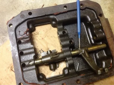
Once both are removed, rotate the shaft until the notch in the middle is visible as shown in the photo by the brass drift pin. It won't be quite that visible at first. Tap the notch with a brass drift and tap it out the same direction as the 3rd-4th shaft (towards the front of the vehicle if it were mounted) and pop the expansion plug. Remove the shaft. Don't lose the small cylindrical interlock pin that seats in the shaft.

image-1191259439.webp
Notch for removal

image-2634415575.webp
Cylindrical pin for middle shaft

Next remove the remaining shaft - the Reverse shaft. Don't lose the oblong interlock pin.

image-1401799644.webp
image-2862640195.webp
Remove the Slotted Spring Pins

Pull the shaft out of the backup light switch hole


image-2353372113.webp
Backup Light Hole
image-2918029360.webp
image-2212731969.webp
image-618636660.webp
image-2736262236.webp
image-2512992993.webp
image-1191259439.webp
image-2634415575.webp
image-1401799644.webp
image-2862640195.webp
image-2353372113.webp
 
Last edited:
I removed all the gears that I could first. I also left the snap ring on the outer race of the bearing to give me something to push against. Making longer arms sounds like a good idea to try.
 
Dang, stuck again.

I must remove the output rear bearing. Long output shaft is in the way of my short puller, and 1st gear won't allow me to drive it from the inside.

Should I just remove the gears from the shaft then drive the bearing out?

View attachment 796304
Nope cannot do that. No room at the shaft end. Case is in the way.


View attachment 796305
Gotta remove this bearing


View attachment 796300
I don't have a long puller.

Ok mudders - how?

I see you have progressed to the point you get to deal with the "PITA" bearing. I have had this bearing frozen to the output shaft on all three transmissions I have worked on. Cutting the bearing apart is best way I have found after breaking pullers and getting no where with my press. I do like Pin_Head's take a swing at it with a 10lb. sledge trick. If for no other reason then to vent after spending hours trying to remove that damn bearing. My old writeup may be of some help to you with your project. My transmission barely failed all the FSM clearance tests and still shifts fine to this day. http://mysite.verizon.net/gogokitty..._Install_/marlin_crawler_toybox_install_.html
 
I see you have progressed to the point you get to deal with the "PITA" bearing. I have had this bearing frozen to the output shaft on all three transmissions I have worked on. Cutting the bearing apart is best way I have found after breaking pullers and getting no where with my press. I do like Pin_Head's take a swing at it with a 10lb. sledge trick. If for no other reason then to vent after spending hours trying to remove that damn bearing. My old writeup may be of some help to you with your project. My transmission barely failed all the FSM clearance tests and still shifts fine to this day. http://mysite.verizon.net/gogokitty..._Install_/marlin_crawler_toybox_install_.html

John - fantastic, thank you for the information, and for your writeup link. It will help me get this done, and help me finish what I started here. I'll be sure to reference your thread at the beginning of mine so that others can use it.

Really appreciate it!!!

I knew there were more folks than were letting on that had rebuilt these things.

Scott (VV)
 
Finally had time to make this tool and get that dad-gum (cursing filter is on) output bearing off.

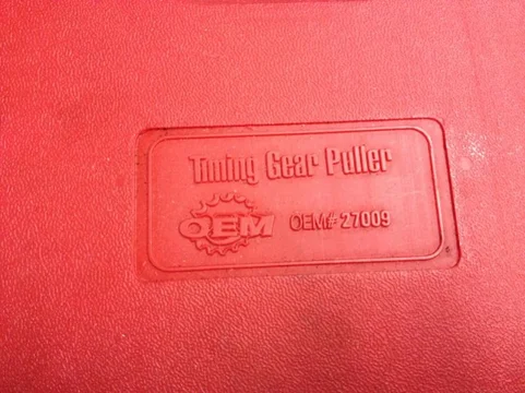
Bought some 7/16 threaded rod (2 x 12" is what I cut off), 4 nuts and 4 washers. Borrowed the Autozone OEM Puller pictured below.

image-273768675.webp
Puller from Autozone Loan-a-Tool

Ground down the rods to fit in the holes and grab the edges. Also ground down one side on the nut end to fit into the puller head. Go ahead and run the grind down several inches in case you need that distance (I did).

image-1396227704.webp
Grind ends

image-2324849840.webp
Assemble the Tool

image-116627411.webp
Ends

image-4234559975.webp

image-2724201202.webp
Requires the screwdrivers to keep the rods in place.

Others fashioned a band around the rods with a captured but and a bolt to keep tension on the rods - pushing inward. I skipped that. KISS.

Other threads show bracing a wrench between the INSIDE of the case and the input shaft so the bearing pulls out. I failed to do that and the shaft indeed pushed in.

At the point I realized I had goofed, I braced the gear on the input side to the case, re-adjusted the puller on the output side so it was tight, gave the input shaft side a single 3# hammer whack and got the bearing moving.

image-3204292080.webp
Had to whack this side with a heavy hammer.

Because I had pushed the shaft in, I had to grind the nut ends of the shafts further down so I could shorten the length of the puller.

I was then able to continue to pull the bearing.
image-3389429616.webp
image-273768675.webp
image-1396227704.webp
image-2324849840.webp
image-116627411.webp
image-4234559975.webp
image-2724201202.webp
image-3204292080.webp
image-3389429616.webp
 
Last edited:

Users who are viewing this thread

Back
Top Bottom