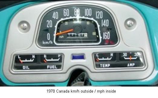
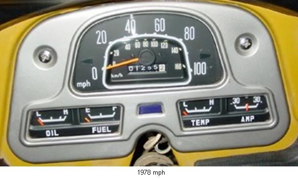
The 3rd generation from Sept. ’72 till Jan. ‘79
EDIT; Jan. 20, 2014 : This text is added later and is the same as in posting #310 which was inserted on Jan. 20 2014
Back to the original posting.....
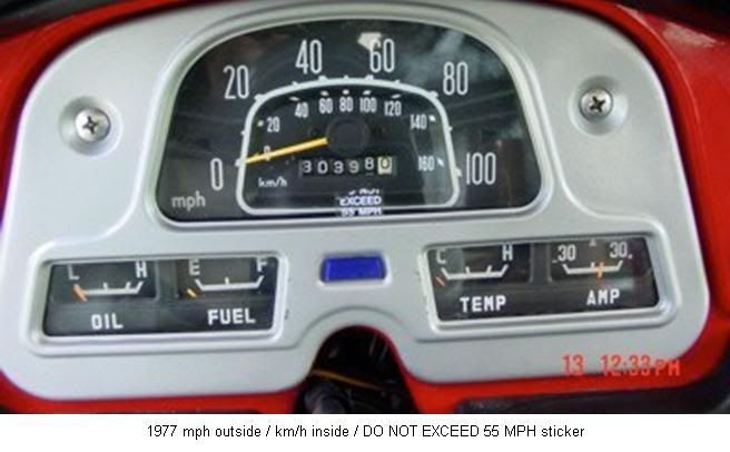
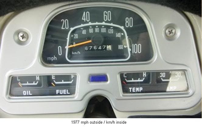
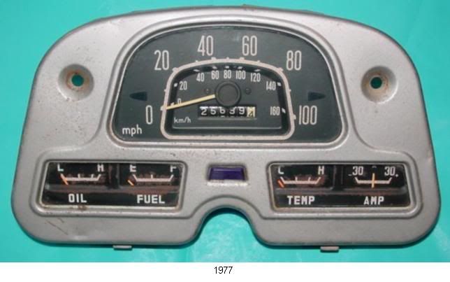
The TEMP and FUEL gauges changed places.
The wiring changed into a barrel connector.
Turn indicators were added into the cluster.
The look of the gauge faces changed a little. The horizontal bar is a bit longer. The sweep range is now 45°. The previous was 40°.
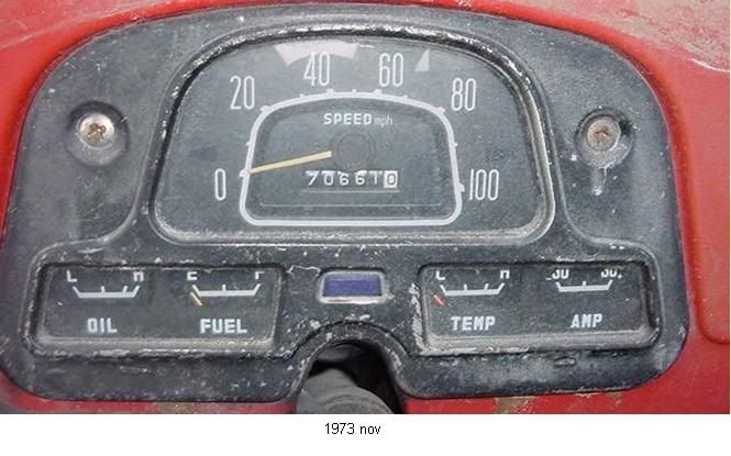
In Sept. ’73 the FJ became also available for the General and European market.
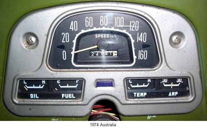
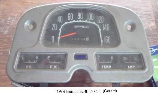
In Feb. ’74 the BJ40 24V edition came into the European and Canadian market. This is not visible when you look at the front of the cluster but will show when you turn the cluster around and look at the back. There is a “dropper” resistor to bring the 24V down to 12V for the FUEL and TEMP gauges. The OIL gauge is different and is clearly marked 24V (after removing the front) in the right bottom of the gauge and has a different sender of course. The AMP gauge is the same for 12V or 24V clusters. More about this in a later posting.
Rudi
View attachment 854117
View attachment 854118
View attachment 854119
View attachment 854120
View attachment 854121
Navigation
Install the app
How to install the app on iOS
Follow along with the video below to see how to install our site as a web app on your home screen.
Note: This feature may not be available in some browsers.
More options
Style variation
You are using an out of date browser. It may not display this or other websites correctly.
You should upgrade or use an alternative browser.
You should upgrade or use an alternative browser.
Clusters, Gauges, Speedo & Odo meters (2 Viewers)
- Thread starter bj40green
- Start date
This site may earn a commission from merchant affiliate
links, including eBay, Amazon, Skimlinks, and others.
More options
Who Replied?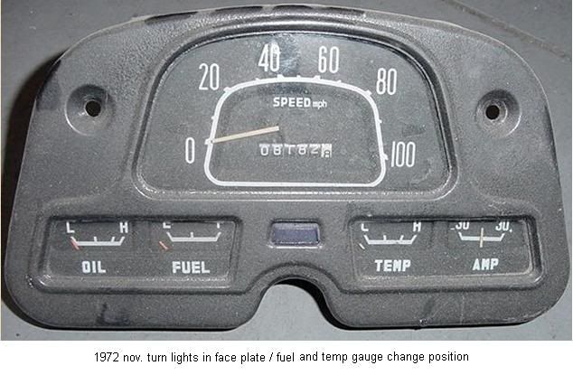

Matt, don't forget about the 73 only cluster that looks like the 72-79 on the front but has the early connections on the back (no circuit board or barrel connector).
i know nothing on that topic russ ?
it looks like you just committed to VOULUNTEAR the time required here to update this thread ?
awesome i can't wait till i see this
good call RUSS
This was very confusing when I first got my truck because it looked like the old style cluster from the back but the insides are from the 74+ cluster.
FJ40Savvy
SILVER Star
Great reference picture.
Is there any chance you know when the back of the cluster change to the version with the large connector, printed circuit board and quarter turn blub holders? I have a 10/72 cluster . It has the front layout of the 09.72-12.78. When I went to do the LED blub upgrade, I used the information in the forum and purchased blubs only to find out that my cluster still has the back of layout of 03.69-08.72. The blubs I purchased didn't fit. For those of us that own 73s, adding a date when the back of the cluster changed to this reference picture would be awesome.
FJ40Savvy
SILVER Star
Looks like @Engineer8000 posted the answer while I was typing my post. Thanks for the informationGreat reference picture.
Is there any chance you know when the back of the cluster change to the version with the large connector, printed circuit board and quarter turn blub holders? I have a 10/72 cluster . It has the front layout of the 09.72-12.78. When I went to do the LED blub upgrade, I used the information in the forum and purchased blubs only to find out that my cluster still has the back of layout of 03.69-08.72. The blubs I purchased didn't fit. For those of us that own 73s, adding a date when the back of the cluster changed to this reference picture would be awesome.
View attachment 2982238
Last edited:
Great reference picture.
Is there any chance you know when the back of the cluster change to the version with the large connector, printed circuit board and quarter turn blub holders? I have a 10/72 cluster . It has the front layout of the 09.72-12.78. When I went to do the LED blub upgrade, I used the information in the forum and purchased blubs only to find out that my cluster still has the back of layout of 03.69-08.72. The blubs I purchased didn't fit. For those of us that own 73s, adding a date when the back of the cluster changed to this reference picture would be awesome.
View attachment 2982238
no , buy my TOP TOP TOP Undercover plain cloths SKUNK WORKS AGENT of teq " paul @Ackcruisers specializes in clusters and is the Laboratories go to dude 24/7
here
Matt, don't forget about the 73 only cluster that looks like the 72-79 on the front but has the early connections on the back (no circuit board or barrel connector).
The famed 5 bulb cluster.
i do NOT play with this style by choice ..
why u ask ?
because in all my travles , i have never suun the actual HYBRID inverted bulbs trist sockets in any way i can obtain one or more as needed ?
why do i need them u ask ?
4.20 times out of 10 the entire sub harness above is simply missing ? bottom line .......

id say , a solid 8 times out of 10 the sub harness needs one or more bulb socket for all the reasons you can think of imaginable ?
this makes restoring one properly by the book not practical since it's a LOCHNESS MONSTER sight to ever see any sub harness's in whole or part offered up on ebay or
MUD ?
my experience ......
however , i have this going on , and a few pre - made at this time too ........
do u know what this is by chance ?
its TEQ pop tech quiz time and u have 1 minute to reply or u face certain DOOM
Great reference picture.
Is there any chance you know when the back of the cluster change to the version with the large connector, printed circuit board and quarter turn blub holders? I have a 10/72 cluster . It has the front layout of the 09.72-12.78. When I went to do the LED blub upgrade, I used the information in the forum and purchased blubs only to find out that my cluster still has the back of layout of 03.69-08.72. The blubs I purchased didn't fit. For those of us that own 73s, adding a date when the back of the cluster changed to this reference picture would be awesome.
View attachment 2982238
The 5 bulb production date should be Sept 1972 to Sept 1973
part #83100-60071
And and you're right, this cluster uses the old style round push in and turn bulbs.
I didnt see the pop quiz of doom til just now.i do NOT play with this style by choice ..
why u ask ?
because in all my travles , i have never suun the actual HYBRID inverted bulbs trist sockets in any way i can obtain one or more as needed ?
why do i need them u ask ?
4.20 times out of 10 the entire sub harness above is simply missing ? bottom line .......
id say , a solid 8 times out of 10 the sub harness needs one or more bulb socket for all the reasons you can think of imaginable ?
this makes restoring one properly by the book not practical since it's a LOCHNESS MONSTER sight to ever see any sub harness's in whole or part offered up on ebay or
MUD ?
my experience ......
however , i have this going on , and a few pre - made at this time too ........
do u know what this is by chance ?
its TEQ pop tech quiz time and u have 1 minute to reply or u face certain DOOM
View attachment 2984018
This looks like a wiring kit to convert old screw in clusters to those fancy new kilometer clusters. Although that white and black wire out of the middle plug is extra I think.
I didnt see the pop quiz of doom til just now.
This looks like a wiring kit to convert old screw in clusters to those fancy new kilometer clusters. Although that white and black wire out of the middle plug is extra I think.
u win
PM me for prize to be mailed out
I have a 71 FJ40 with a 2nd generation cluster and a F1.5 engine from a 73 that I've been rebuilding. It has an early style Temp Sending Unit that should match my cluster. When off, the needle sits past H as it should. When on and the engine warmed it, it doesn't move to an appropriate spot on the gauge. If I ground the wire from the gauge straight to the battery, the needle goes straight to C, take it off and goes back past H. Is there a way I can test an early Temp Sending Unit? I read through this and found OHM reading for the later units, but didn't see any numbers for the earlier sensors. I've gone through enough money on this project and the early sensors are over $40, more than I'd like to spend just guessing. With engine warm and running the resistance fluctuates rapidly but stays between 45 - 60 between the top of the sensor and the block. I also measured between the top of the sensor and the side of the sensor, similar resistance.
You say early style sending unit but I think the sender changed between 72 and 73. The pre 73 sender is different. This is the resistance for the 73 and + sender. @ToyotaMatt may have some inside info on the pre 73 sender.

middlecalf
SILVER Star
I’ve hunted around a little for the early sender ohm data, this is all I’ve found so far, empirical data (early for me is at least ‘65 or ‘63):

 forum.ih8mud.com
I read somewhere else on mud (can’t recall where though ) that resistance measuring is not a sufficient way to determine the validity of the early temp senders. You can see in the attached thread link that Jim @Cruiser_Nerd saw very little resistance drop once the coolant (ambient) temperature started to rise into the working range. FWIW. I’m curious about this now on my ‘63 FJ45 (‘64 F135 motor) as just recently I’m getting lower readings with nothing really changed, so not sure if it’s a sensing/gauging issue or a coolant/thermostat issue. Despite motor age the components in the cooling system are new (temp gauge is original).
on edit: I strongly suspect an air bubble in my system, esp. since the heater hose that runs from the fitting that the temp sender unit is in over the rear of the engine into the heater core is the highest part of the cooling system so I probably have an air bubble that's keeping hotter coolant from the sensor. Time to burp!
Temp Sender for Early Cluster.
Checked these values for Splangy, thought I'd post it up in a thread since I didn't see it in our old conversations. I believe this applies to all the early 25 and 40 clusters. I did a few readings on a working stock sender so we could have a record of the values, unfortunately it wasn't too...
forum.ih8mud.com
I read somewhere else on mud (can’t recall where though
) that resistance measuring is not a sufficient way to determine the validity of the early temp senders. You can see in the attached thread link that Jim @Cruiser_Nerd saw very little resistance drop once the coolant (ambient) temperature started to rise into the working range. FWIW. I’m curious about this now on my ‘63 FJ45 (‘64 F135 motor) as just recently I’m getting lower readings with nothing really changed, so not sure if it’s a sensing/gauging issue or a coolant/thermostat issue. Despite motor age the components in the cooling system are new (temp gauge is original).on edit: I strongly suspect an air bubble in my system, esp. since the heater hose that runs from the fitting that the temp sender unit is in over the rear of the engine into the heater core is the highest part of the cooling system so I probably have an air bubble that's keeping hotter coolant from the sensor. Time to burp!
Last edited:
Thanks for that post, it is interesting the resistance doesn't change from 102F to 180F. If the resistance isn't an accurate way, what is? What is the gauge reading?I’ve hunted around a little for the early sender ohm data, this is all I’ve found so far, empirical data (early for me is at least ‘65 or ‘63):
Temp Sender for Early Cluster.
Checked these values for Splangy, thought I'd post it up in a thread since I didn't see it in our old conversations. I believe this applies to all the early 25 and 40 clusters. I did a few readings on a working stock sender so we could have a record of the values, unfortunately it wasn't too...
I read somewhere else on mud (can’t recall where though
on edit: I strongly suspect an air bubble in my system, esp. since the heater hose that runs from the fitting that the temp sender unit is in over the rear of the engine into the heater core is the highest part of the cooling system so I probably have an air bubble that's keeping hotter coolant from the sensor. Type to burp!
Thanks, yes the sensors changed. I put an early sensor onto my 73 motor so it matches the gauge in my cluster.
You say early style sending unit but I think the sender changed between 72 and 73. The pre 73 sender is different. This is the resistance for the 73 and + sender. @ToyotaMatt may have some inside info on the pre 73 sender.
View attachment 2993324
Thanks, yes the sensors changed. I put an early sensor onto my 73 motor so it matches the gauge in my cluster.
I see that now after I re-read your post. I was confused. Is it possible you used thread sealant and the body of the sender is not grounded to the engine?
No sealant. It's connecting well with the block, the resistance between the block and base of the sensor is almost 0.I see that now after I re-read your post. I was confused. Is it possible you used thread sealant and the body of the sender is not grounded to the engine?
As a gross check you could verify your sender resistance increases with temperature to at least verify it is functioning and in the correct direction. Unlike the 73+ sender this one should have low ohms when cold ( more current to drive the gauge over to C) and increase resistance as it heats up (lower current to let gauge move back home to H). I've seen numbers stated like 50 ohms cold and 150 ohms hot but I am not positive that is correct.
Similar threads
Users who are viewing this thread
Total: 3 (members: 0, guests: 3)