CDL relay removal (1 Viewer)

This site may earn a commission from merchant affiliate
links, including eBay, Amazon, Skimlinks, and others.

Skidpad13

SILVER Star
Joined
Sep 30, 2021
Threads
4
Messages
22
Location
Nashville, TN
Hey folks, I've searched the forums but no one has mentioned exactly HOW to get the relay out to do the 7 pin mod or test the relay. I've gotten the ABS module out of the way (sort of, I had to un bolt the brackets as those 4 tiny Phillips head screws are locked in with force). Now that I've got the relay exposed how on earth do I get it out? I'm upside down twisted sideways & cannot figure it out with any sort of delicate approach. I'm not quite ready to go full unga-bunga on it since there are so many tiny wires in that small space. Any advice on how to release the relay from whatevlding it would be greatly appreciated. Thanks all!
 
Are these the instructions you are following?

 
Yep, but my question is for a more detailed explanation of "unplug the harness" in particular i want to remove the relay from the truck so i can test the relay on the bench. I can't figure out how to get the relay to release from whatever is holding it into the truck. My Center Diff light isn't lighting so I want to test the relay before I proceed to removing the actuator from the top of the T-case. Thanks!
 
Here's a back view from the web. Is it really just a matter of one screw that I didn't see?
20220215_195328.jpg
 
My Center Diff light isn't lighting so I want to test the relay.....
Just so you know, the relay doesn't control the CDL light, that's done by the switch on the front of the T-case.
 
Yep, sorry, I should have been more clear. I've gotten the light to come up with the paperclip test. I'm eliminating the relay by doing the FSM test. I've done my 'flow chart' from the EWD. Thanks for keeping me between the lines!

I'm also wanting to get the 7 pin mod done while I'm in there since I've already installed the CDL switch on the dash.

Thanks again!
 
When you did the paperclip test did you also remove the sensor switch and test continuity when manually testing on the bench? Seems like you are trying to do the most difficult thing before doing all the simple things first. When you press the CDL switch are you hearing any clicks or the actuator noise for a couple of seconds?
 
When you did the paperclip test did you also remove the sensor switch and test continuity when manually testing on the bench? Seems like you are trying to do the most difficult thing before doing all the simple things first. When you press the CDL switch are you hearing any clicks or the actuator noise for a couple of seconds?

Agree, rule out the sensor switch first before going further.
 
Sorry guys, when I first posted this I didn't follow rule number one and take the time to explain the situation in detail or to list what I've already done. Totally my fault for not following good posting procedures. So:

Yes, I've replaced (after testing) the switch on the top of the transfer case. I've installed the dash switch but no sound from the relay or the actuator motor when it's pressed. I have not yet tested the neutral position with or the low position switch on the back of the transfer case.

I have not taken battery voltage directly to the actuator motor but plan to if the relay is good.

The reason I want to remove the relay is twofold: I want to test it and I want to go ahead and do the 7 pin mod while I'm down there.

Once I have this complete, assuming that the relay is good but the center still won't lock, I will perform the FSM impedance/continuity test on the wiring harness to the actuator motor.

If that test comes back ok then I'll apply 12v to the actuator motor contacts & see if it engages/disengaged. If it does then I'll start checking wiring for problems. If it doesn't, then I'm dropping the crossmember a few inches and I'll remove the actuator motor.

With all that said, my question is ridiculously simple. What's the magic trick for getting the relay released from the side wall of the vehicle? I'm guessing that it may just be one screw from research on the web parts sites but I always want to check the group here to see if I'm missing something easy.

Thanks to everyone for this group, it's awesome!
 
02_21_2022 - Update: Hello folks; with the break in the weather here I was able to get back out and finally get the relay out for testing as well as doing the 7-Pin mod.
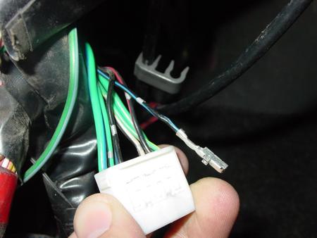
Here are some images to help those real 'color-by-numbers' guys like me.

The relay is held in with a bracket that is inserted into the far side (towards firewall) of the relay. Given the age of the plastic, I didn't want to try and compress the tab in the relay case to get it to release from the bracket so instead I unscrewed the two 10mm nuts that hold the adjacent relay (it was blocking access to the nut that is holding the CDL relay) and the CDL relay brackets. See image below for context. The firewall is to the right.

1645462464851.jpeg


Once the two nuts were successfully removed, I got the bracket and relay back onto the bench for testing. Here are three shots showing the relay case (for those that need the part number), the end of the relay that corresponds with the graphic in the FSM, and the internals of the relay showing the actual relays and diodes.

1645462632573.jpeg


1645462688336.jpeg


1645462731650.jpeg


Once I had the relay inside I followed the FSM testing procedure. I have continuity between pins 1&2, 2&4, but when I tested for continuity across the diode at pins 6&7, I had super high impedance (over 570 ohms when leads were oriented one way relative to polarity, and then nothing when they were reversed). So I moved on to the battery positive voltage tests. I do not have continuity between pins 1&3 when battery positive is applied to pins 5&6.

So, I'm not an electrician or a mechanic (I'm an architect) but I do know my way around circuits and multimeters fairly well.

Can anyone on here see anything I've messed up or does the collective mind think that my relay is shot and needs to be replaced?

The only thing I have left as a full Center Diff Diagnostic is 1: to apply 12v power (via a 9 volt battery in series with 2 AAs) to the motor actuator and 2: to test the continuity of the neutral position switch and the low position switch.

Thanks for anyone's advice on this. I don't mind replacing the relay but I'd like to avoid that expenditure if possible.

Cheers!
 

Users who are viewing this thread

Back
Top Bottom