Alternator Hot Wire Corroded (1 Viewer)

This site may earn a commission from merchant affiliate
links, including eBay, Amazon, Skimlinks, and others.

Joined
Feb 26, 2015
Threads
65
Messages
291
Location
Coweta, OK
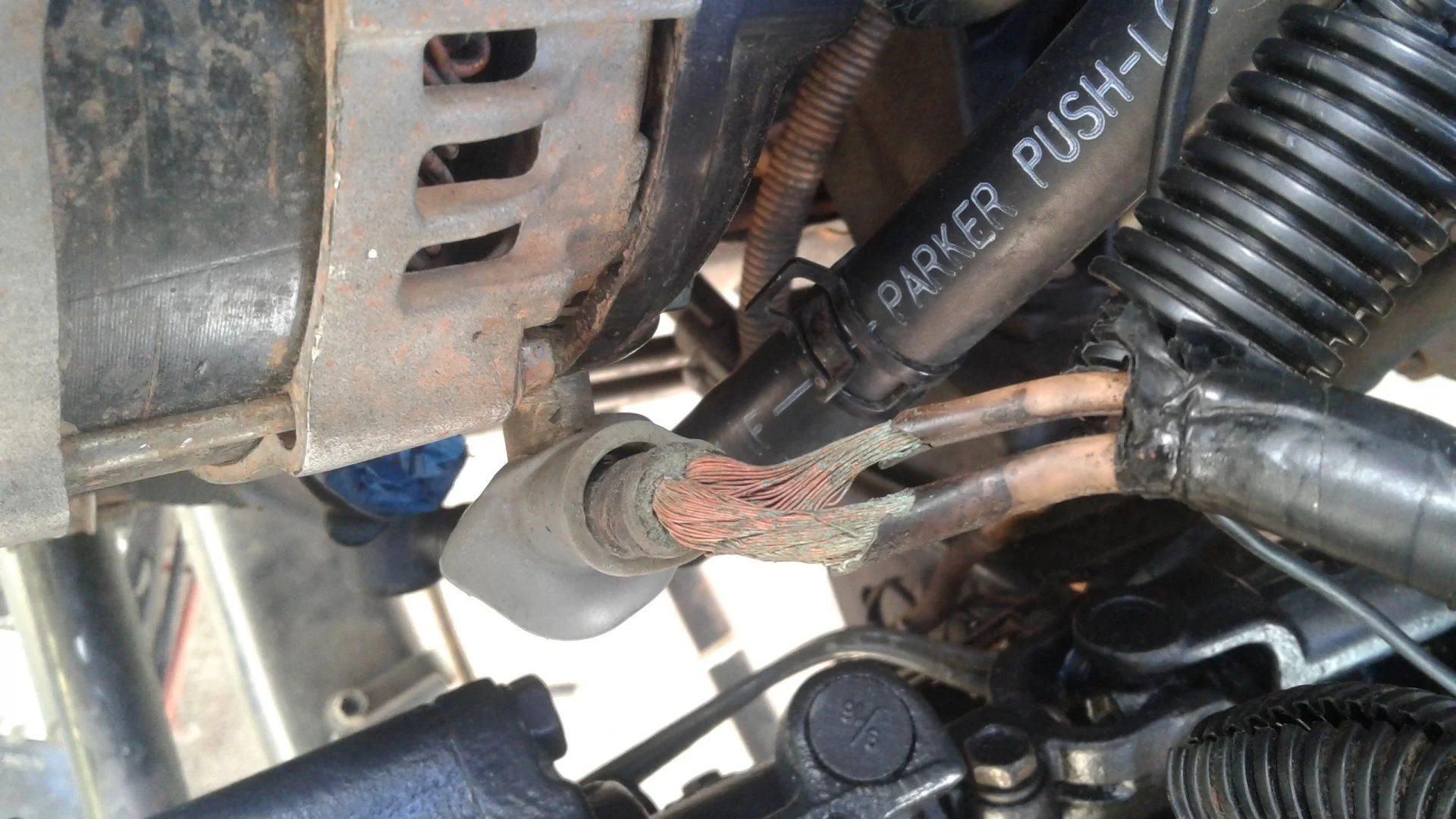
So today I was putting in my rebuilt steering gearbox and noticed green dust falling when I touched the big alternator wire. I found that the hot wire was pretty corroded.

and now,,, I'm looking for a bit of help here, Since I'm running the Sequoia Alternator (with Photomans'bracket)....

what would be the best way to repair this?
How difficult would it be to upgrade this to a thicker gauge wire? ... where do these wires run to? I'm kinda stumped.

 
Deoxo it put silicone around, it be done
 
It's pretty are up all the way through and coming unwound. I'm not sure I'd trust it at all.

I could splice out the bad section, but could I not run a line directly to the battery?

I'm just confused why there are 2 wires going into the one lug, I thought that was out to the battery.
 
It's pretty are up all the way through and coming unwound. I'm not sure I'd trust it at all.

I could splice out the bad section, but could I not run a line directly to the battery?

I'm just confused why there are 2 wires going into the one lug, I thought that was out to the battery.

Well you can either peel it back all the way through, the harness and rewire, or peel it back to where it is corroded stops, Deoxit let dry use some high temp silicone and re-shield it, as long as it's charging fine, I would do this
 
It looks like you didn't upgrade your wiring when in put in the Sequoia alternator. The original stock alternator could put out 80A, while the Sequoia is capable of 150A. Upgrading the wiring with the new alternator is considered mandatory. Either in the original @Photoman bracket thread or a related thread there was a bunch of discussion on the best way to go about upgrading the wiring. Leaving yours as is may leave you stranded someplace in the future when the splice between those existing wires fails. This it a well-documented trouble spot.
 
It looks like you didn't upgrade your wiring when in put in the Sequoia alternator. The original stock alternator could put out 80A, while the Sequoia is capable of 150A. Upgrading the wiring with the new alternator is considered mandatory. Either in the original @Photoman bracket thread or a related thread there was a bunch of discussion on the best way to go about upgrading the wiring. Leaving yours as is may leave you stranded someplace in the future when the splice between those existing wires fails. This it a well-documented trouble spot.

That is a good point, that I missed, yes the 150a VS 80a is a little more taxing on the wires
 
Nope. I did not upgrade the wiring. I only installed the bracket and smaller pulley with the 150 generator. My searches for this did not come up with much, but a re-read of page 2 of the alternator upgrade thread tells me I missed something. Thanks. :beer:

I know what I'll be doing tomorrow!

Btw, I have a 2nd battery with solenoid amd marine switch. ...it. is my understanding that the b+ goes to the main battery... not both. Right? :confused:
 
Last edited:
One of those wires leads to the battery. The other leads to the fuse/relay box. Shouldn't t be a problem to replace them.

I would get the battery box out of my way first and maybe even the vapor canister bracket as I prefer space to work.

I know that a lot of people upgrade to 4 AWG when going to the 150a alternator but that's overkill. The wires you have are equal to 8AWG in size and capable of handling 150a for the very short distance that it extends.

I'm no guru, this info is easily found all over the internet. Your problem is corrosion. If you wanted to ease your pain you could run an 8AWG, or 6 if it makes you feel warm and fuzzy, charge wire, incorporating an inline fuse, directly from Alt. to your battery.

Or, chop the old wires off an inch at a time until you come to clean wire and then splice new segments in.
 
So, forgive my ignorance, but why does the alternator b+ need to go to the fuse box? Why does the battery + not go to the fuse box? What (obviously important) role does this play? Thanks.
 
My memory may be failing me here. It's always best to refer to the fsm and accompanying wire diagrams.
 
Thanks for setting me straight.
 
IMG_4898.PNG
https://static1.squarespace.com/sta...442806549877/1996+Toyota+Land+Cruiser+EWD.pdf
 
The image @baldilocks posted above is only the charging circuit. That's not the complete circuit relevant to the alternator and therefore not the complete story. The more relevant page is the from "power source" section of the EWD:

PowerSource2.png


The orange oval indicates the deteriorating splice shown in the original post. In original stock form the white wire from the alternator to the fuse block is ~7 AWG and the white wire from the alternator to the fusible link is ~6 AWG. If you look a few pages into Bill's alternator upgrade thread (Upgrading stock alternator to 130/150 amp) you'll see most people are changing out the 6 gauge wire for a 4 gauge wire that is run to the positive battery terminal through a 150A fuse.

The original poster will also need to repair the damaged 7 gauge wire by stripping the insulation back to the point of good copper conductor and then splicing on a replacement wire. There's plenty of discussion about all of this in the alternator upgrade thread.
 
The image @baldilocks posted above is only the charging circuit. That's not the complete circuit relevant to the alternator and therefore not the complete story. The more relevant page is the from "power source" section of the EWD:

View attachment 1468785

The orange oval indicates the deteriorating splice shown in the original post. In original stock form the white wire from the alternator to the fuse block is ~7 AWG and the white wire from the alternator to the fusible link is ~6 AWG. If you look a few pages into Bill's alternator upgrade thread (Upgrading stock alternator to 130/150 amp) you'll see most people are changing out the 6 gauge wire for a 4 gauge wire that is run to the positive battery terminal through a 150A fuse.

The original poster will also need to repair the damaged 7 gauge wire by stripping the insulation back to the point of good copper conductor and then splicing on a replacement wire. There's plenty of discussion about all of this in the alternator upgrade thread.
Thanks for proving that my memory isn't as cloudy as I was beginning to believe. I was quite sure that the second white cable went from the alternator went to the fuse/relay box.

According to several charts I have seen over the years, 10 AWG is sufficient to handle 150a over such a short distance. Once again Toyota over did it by going to a 6 AWG charge wire with an 80 amp alternator.
 
Yep! Pretty much confirms exactly what I plan to do. I have some leftover #2 welding wire so that's what I'll use. I have a marine fuse box with 150A slow burn bus fuse, and im just gong to run fresh #6 to the fuse box. Since my #2 battery is connected via solenoid to my main battery I won't need a b+ wire for it. Thanks. :beer:
 
Yep! Pretty much confirms exactly what I plan to do. I have some leftover #2 welding wire so that's what I'll use. I have a marine fuse box with 150A slow burn bus fuse, and im just gong to run fresh #6 to the fuse box. Since my #2 battery is connected via solenoid to my main battery I won't need a b+ wire for it. Thanks. :beer:
Which charts dictated a giant #2 cable or anything larger than what's there already? I'm curious and want to be sure that the info I have gone by is not erroneous.
 
Did you not see the orange oval?!?!? :rofl:

Naw... My understanding from the 150a alternator upgrade thread was that a slightly larger gauge cable was recommend. (I'm running a dual battery with the 150a sequoia generator)

I have some leftover 2# from the dual battery install and thought I'd just go beefy rather than buy more cable. If you have the stock alternator then you dont necessarily need the thicker wire.

FWIW, I did read that upgrading the fuse box wire seems to improve window motor function.
 
Which charts dictated a giant #2 cable or anything larger than what's there already? I'm curious and want to be sure that the info I have gone by is not erroneous.

If we say circuit length is 6-7 feet (alternator to battery, battery to ground block) then according to this calculator using 2 meter circuit length, 12 vdc, 150 amps, 5% acceptable loss, recommended wire size is 4 AWG. With 3% acceptable loss, wire size is 2 AWG.
Plugging in the 80 amp alternator with the above and with 5% acceptable loss, recommended wire size is 6 AWG which agrees with what TrickyT said was the stock wire size.

Bill
 
Thanks Bill. Your bracket has made my rig so much more capable. Many thanks to you, sir!
 

Users who are viewing this thread

Back
Top Bottom