Navigation
Install the app
How to install the app on iOS
Follow along with the video below to see how to install our site as a web app on your home screen.
Note: This feature may not be available in some browsers.
More options
Style variation
You are using an out of date browser. It may not display this or other websites correctly.
You should upgrade or use an alternative browser.
You should upgrade or use an alternative browser.
1978 LPB Teardown and Rebuild
- Thread starter Awl_TEQ
- Start date
This site may earn a commission from merchant affiliate
links, including eBay, Amazon, Skimlinks, and others.
More options
Who Replied?Awl_TEQ
Supporting Vendor
- Thread starter
- #104
A couple of my start on the roll cage. I've got most all of the main pieces bent, I just have to trim and notch to fit. I started in the rear corners, offset forward to clear the tub/back joining flange, offset inward to bring the tube up between the windows, 90+ deg. bend angled out to the top of the door frame to the windshield frame and across the top of the windshield. There will be tubes run across the back at the top and bottom behind the seats. Also two tubes will come down the 'A' pillars and through the dash then to the floor. The 'A' pillars will be connected across the dash. The stock dash pad will be removed and I will replace it with a custom dash and storage locker.


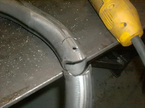
I'm going to have to splice in a couple of places. The ID of my 1-3/4" DOM is 1.510" so my 1.5" OD tube makes a perfect sleeve. Three plug welds on each side of the splice and a full weld around the joint. In this shot only the bottom plug welds are done.
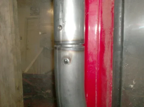


I'm going to have to splice in a couple of places. The ID of my 1-3/4" DOM is 1.510" so my 1.5" OD tube makes a perfect sleeve. Three plug welds on each side of the splice and a full weld around the joint. In this shot only the bottom plug welds are done.

Awl_TEQ
Supporting Vendor
- Thread starter
- #105
Okay - so today I planned on just cleaning up the mess I made of the garage last weekend, but having escaped the house cleanly I started finishing the rear sliders.
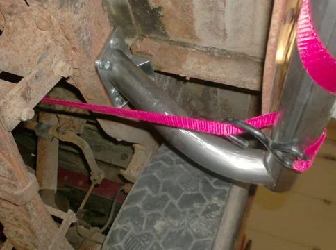
Here is where I left it last week. I need to run a tube from the mount I made on the frame to the slider.

I have some scraps of bent tube.
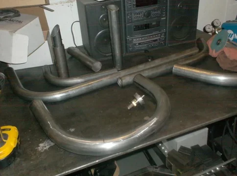
And a slightly primitive way of notching the tube.


Here is where I left it last week. I need to run a tube from the mount I made on the frame to the slider.

I have some scraps of bent tube.

And a slightly primitive way of notching the tube.

I see you have the same problem as me with the rubber dampeners on the anti-sway bar. I can't for the life of me get them to stay in the bracket.
I love the rear bumper. I may have to do something like that on mine someday.
I love the rear bumper. I may have to do something like that on mine someday.
Awl_TEQ
Supporting Vendor
- Thread starter
- #109
Yeah, there's nothing really holding them in with all the twisting pushing them out. I may make a new retaining bracket with ends on it to help stop it slipping out.
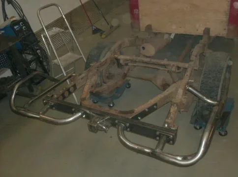
So I started early (relatively) this morning. Got the rear bumper/ slider finished save for welding and powder. Here are a bunch of pics.....
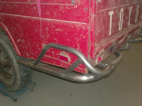


So I started early (relatively) this morning. Got the rear bumper/ slider finished save for welding and powder. Here are a bunch of pics.....


Wow! Nice work, Looks great!
I wish I could work as fast as you. I hardly have time to keep up with your build there's so much progress each week. I just realized you are starting on the cage as well (after looking at all the pictures)  Have you decided how you will be mounting the cage to the floor in this area? I'm trying to decide how I'll do mine and I'm interested to see what you come up with.


 Have you decided how you will be mounting the cage to the floor in this area? I'm trying to decide how I'll do mine and I'm interested to see what you come up with.

Awl_TEQ
Supporting Vendor
- Thread starter
- #116
Mike
I did all the tube bending I could all at once because my buddy uses his tube bender for a living (he has a one man welding shop specializing in custom motorcycles and exhaust headers, even a jet helicopter kit he built for one guy) - so I couldn't keep it very long. Now I have a bunch of random looking bent tube that I have to trim, notch and fit/ weld into something.
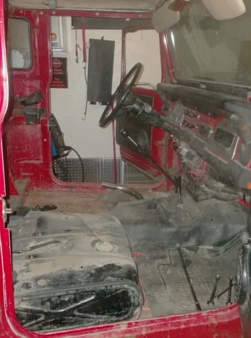
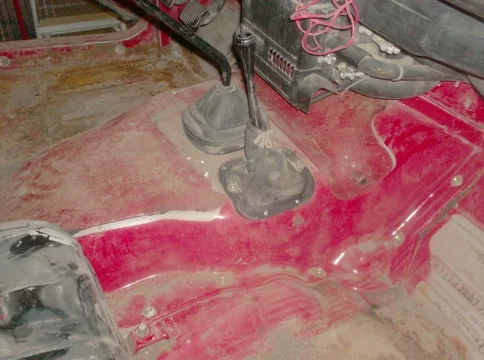
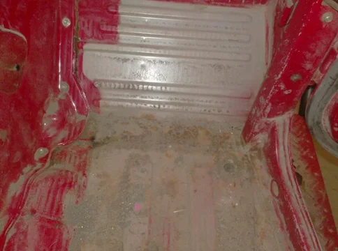
At the moment the cage is just tacked to the floor for fitting up. I plan to actually cut a 4"x4" or so hole through the "bench" and drop in a small 4" extension with a plate on both ends. It will bolt through the bottom floor and to a bracket off the frame. I don't see the point in making a roll cage that is not connected to the frame. The 4" extension will be "sheeted" over so that all you will see if you remove the cage is four threaded holes in the "bench" both inside and underneath. This arrangment does present an issue with regard to body flex. The cab is rubber mounted to the frame, the cage is solid to the frame and the cage is solid to the cab. That could be interesting when flexing the frame. Not sure what, if anything will come of it though. Maybe just a little movement between the cab and cage. I am trying to leave a half inch or more between cab and cage but also trying to preserve what little volume there is inside the cab as well as visibility through the 'A' pillars. Another consideration is that I want to be able to routinely remove the top and back of the cab for that open air feeling. The cage also must be bolt in.
I am going to finish the main sliders next followed by the front brush guards - then the cage. Hopefully all done in about three weeks(ends). Then the box gets blasted and torn apart/ rebuilt. Then the drive train swap,then, then.... oh crap! lotsa work ahead! One step at a time. I think I need a

Thanks for that explanation of how you plan to mount the cage. I've been visualizing something similar to that but I was trying to figure out how to do it without cutting a big hole in the shelf. I may end up cutting that hole as well or I've also been considering removing the front of the "bench" or "shelf" from side to side and then this would serve 2 purposes. One would be to clean, inspect, de-rust and repair any damage under the "shelf" and the second would be to build a short 4" tube section with plates/nuts on both ends which could be slid in and mounted in the now open shelf area before welding the front back on. Like you, I would bolt the cage to this short section of tube/plates from the top and then bolt a support to the bottom which then goes to the frame. To address the flex, I plan to mount the frame to cage supports using urethane bushings. I've done the urethane mounts on my fj40 and its been that way for years without any issues that I can detect.
To remove the front of the shelf, it will require about a zillion more spot welds to be drilled out as well as the two box like brackets between the shelf and door frame. I also think the cab might become too flexy with these removed so bracing the cab first would be a good thing.
Another option would be to create a removable door or plate in that area for the cage. And then create another one or two in the middle sections for cleanout under the "shelf".
Awl_TEQ
Supporting Vendor
- Thread starter
- #118
Mike,
So, these bushings for the cage - they would be under the cab where the cage comes 'through' the floor? Just thinking out loud here... a nice sturdy bracket affair off the frame with a poly bushing on it that the cab/cage sits on and bolts to... that would work I think. The cab may be rubber mounted but in all reality it doesn't move much, and the cage would then be mounted in the same manner.
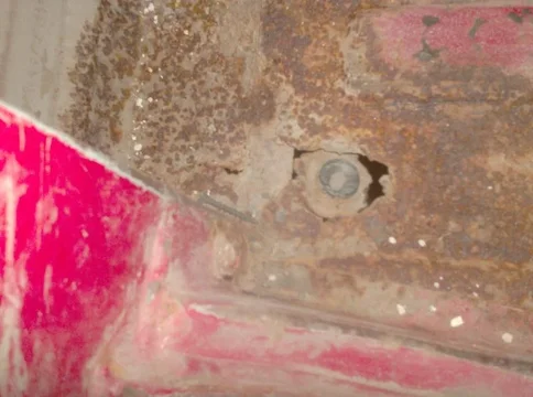
Have you looked at the rear cab mount lately? The spot where the cage will come 'through' the floor is just outward of the "X" shaped bracing for the cab mount. So what I am getting at is this - how to build a mount for the cage when the stock mount is at that spot on the frame? I have toyed with the idea of removing the factory cab mount bracket altogether and fabbing up my own that not only picks up the cab mount but extends out further and picks up the cage as well. I would beef it up accordingly and make it in the original Toyota style, just longer.
The 'A' pillar drop has a similar issue with the front cab mount - maybe a similar solution?
I just had another though with regard to the rear cage to frame mounting. What if, since we are cutting the shelf anyway, we run heavy angle accross the cab inside the shelf. Then the cage would come down on the angle and we would then anchor the angle to the stock cab mounts (maybe beefed up some how). This idea doesn't mount the cage directly to the frame but it does tie the cage to the cab in a way that they would never separate in a roll over. (and if they did you'd have bigger problems anyway). The cab could separate from the frame but that would be in a severe collision or a tumble down quite a hill and the cage (with you in it) would still be intact.
Thoughts?
Right, I used the poly bushings at the underside of the cab (or tub in the case of the 40) and then fixed/rigid mounted the other end of the support at the frame. This allows the cage to flex a little and hopefully not flex and stress the sheetmetal on the cab/tub where the cage mounts.Mike,
So, these bushings for the cage - they would be under the cab where the cage comes 'through' the floor? Just thinking out loud here... a nice sturdy bracket affair off the frame with a poly bushing on it that the cab/cage sits on and bolts to... that would work I think. The cab may be rubber mounted but in all reality it doesn't move much, and the cage would then be mounted in the same manner.
Ah, yes, you are right. But I believe (I will have to look again when I have more time to confirm) that what I planned to do would still work but it may be easier to tie the cage into the existing cab mount like you suggested. However, part of the benefit of the tie in brackets going to the frame is that they would give an extra mount and strength to keep the cab attached to the frame if something really bad or violent happened. Otherwise, you rely on the 4 stock cab bolts which are about 3/8” (10mm) in diameter.Have you looked at the rear cab mount lately? The spot where the cage will come 'through' the floor is just outward of the "X" shaped bracing for the cab mount. So what I am getting at is this - how to build a mount for the cage when the stock mount is at that spot on the frame? I have toyed with the idea of removing the factory cab mount bracket altogether and fabbing up my own that not only picks up the cab mount but extends out further and picks up the cage as well. I would beef it up accordingly and make it in the original Toyota style, just longer.
Here, I can use exactly what I did on my 40. Let me see if I can get some pics of this and post up.The 'A' pillar drop has a similar issue with the front cab mount - maybe a similar solution?
I’m not positive, but I think I understand where you would mount the angle and that seems like it would definitely help to strengthen up the cage to cab structure. It still seems to do nothing for the cage to frame integrity since you are relying on the same 4 bolts. What it would do, is allow more options for tying the cage/angle to the frame since now you have a structure going all the way across the cab. Intriguing idea. I’ll have to think about that one some more.I just had another though with regard to the rear cage to frame mounting. What if, since we are cutting the shelf anyway, we run heavy angle across the cab inside the shelf. Then the cage would come down on the angle and we would then anchor the angle to the stock cab mounts (maybe beefed up some how). This idea doesn't mount the cage directly to the frame but it does tie the cage to the cab in a way that they would never separate in a roll over. (and if they did you'd have bigger problems anyway). The cab could separate from the frame but that would be in a severe collision or a tumble down quite a hill and the cage (with you in it) would still be intact.
Thoughts?
I plan to mount the seat to the cage so staying with the cage in a collision/accident is a good thing but I kind of like the idea of the cab staying on the frame as well. Maybe we are over building but I guess that is better than under building.
I found one picture I had of the front cage-to-frame tie in mounts. Not that good of a picture but I did some crude scetching on the second picture to hopefully point out what it is you are looking at. Picture is taken from underside of the truck and the red part is a metal bracket and mounts with two red bolts to the frame at the front body mount horn. The blue is a metal plate at the underside of the body. There is a similar plate inside the cab and the roll bar is welded to this plate in the cab. The two plates are bolted together sandwiching the body between the two plates. The one you are looking at is on the underside (of course) and it has two tabs welded to it which then are drilled for a 5/8" bolt which goes through a spring bushing (orange) and then the red metal part. The red metal part has a tube on the upper end where the spring bushings are located. This is really the same way a number of motor mounts are built.


Last edited:
Similar threads
Users who are viewing this thread
Total: 1 (members: 0, guests: 1)

