8274 modification and overhaul (for the 105) (1 Viewer)

This site may earn a commission from merchant affiliate
links, including eBay, Amazon, Skimlinks, and others.

Joined
Mar 9, 2009
Threads
10
Messages
310
Location
Western Australia
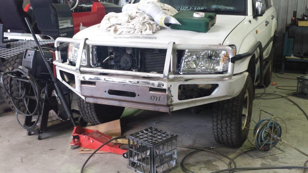
I have a 105 series and I've been doing it up now for a couple of years.

So when it came to choosing a winch, the trusty WARN M8274 high mount came highly recommended. It's known to be a strong, reliable, and proven old school winch that's still widely used around the world.

I hunted around for a couple of months and eventually I found a reasonable 2nd hand 8274 on Ebay for AUD$810 delivered (from a guy in South Australia who said it was in his shed for over 10yrs. Seem a lot of people have these in their shed for many years before deciding to part with it). To me it seemed to be in good working order and was only missing the rope + hook.

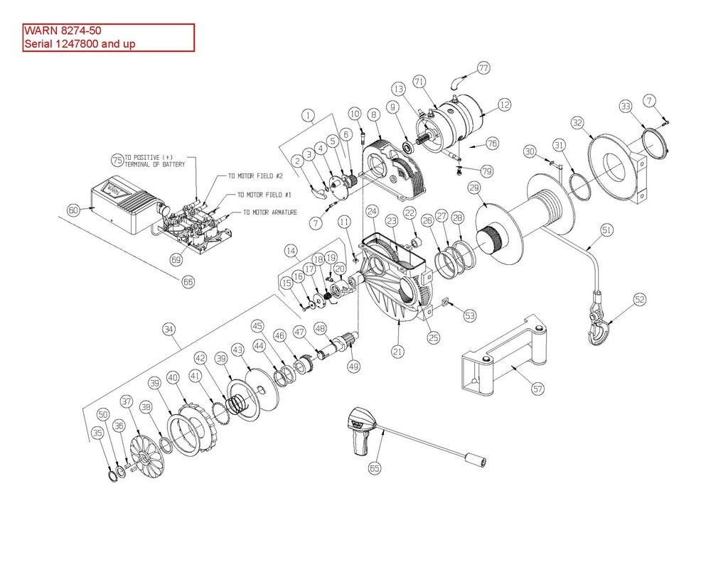
The parts list and exploded diagrams for the various 8274 iterations are here:- Warn Industries - Replacement Parts


Unless you have a really old winch (like mine which predates serial# 348069), then you need to look here beacuse for some reason it's not / or I couldn't find it on the WARN website:- http://www.dojodesign.com/toyota/warn/M8274_RPL_Old.pdf


This is how it looked when I unpacked it.


From what I have gathered, the motor fitments are like this:-
1974 to ~1986 - Prestolite motor / model MRV-B-3 rated @ 2.1HP with keyed shaft
~1987 to 1998 - Bosch motor / model MRV-B-4 rated @ 2.5HP with splined shaft
1998 - present - Warn motor / Warn Part# 7536 rated @ 4.6HP
Alternative - Warn motor / Warn Part# 68608 rate @ 6HP

I've never owned an electric winch before, and never seen an 8274 in action though I did have a PTO winch on my 60 series for the best part of 10yrs. Even so this electric winch stuff is all quite new to me so I had some homework to do on the 8274. I was surprised at how much info there was available, and easy to find!

Here are a few threads I found / some good write ups on 8274 modification and overhaul:-
How old is your Warn M8274 ? - Patrol 4x4 - Nissan Patrol Forum
Rebuilding the legendary Warn M8274 electric winch step by step
Warn 8274 rebuild
My WARN 8274 rebuild part 1.....
Stronger Warn 8274
Warn 8274 experts, CONVERGE!!

I wanted to overhaul the winch regardless and after reading all this info, I also decided to make a few mods at the same time. Being a fitter / turner in a fabrication business, most of the mods below turned out to be quite cheap and easy, though the +76mm GP drum is a little expensive. And so is the synthetic rope if buying the branded material.

Mods on the wishlist for this winch build:-

1) Fit drain and fill plugs to the main housing
2) Brace the floating end support
3) Fit improved friction material in the brake assembly
4) Drill and tap the brake shaft, machine washer to fit (to prevent circlip from flying off)
5) Drill and pin the OEM free-spool lever (to prevent untimely disengagement)
6) Drill and tap the brake pawl, fit grease nipple
7) Install Allbright solenoid pack
8) Fit +76mm Gigglepin air free-spool drum
9) Fit SS Hawse fairlead with synthetic rope and safety thimble
10) Fit high-output 6HP Warn motor


Before doing anything I hooked some jumper leads to the solenoid pack and tested it as best I could (there was no winch cable or bar to mount the winch to). Even so everything seemed to be in good working order, no problems yet!

Then it was time to strip down the winch, and once I had it apart I thought it looked pretty good considering it's from 1983 and more than 30yrs old!


I'm interested to see the real condition of things once all is stripped and cleaned, and to see what prices are for the necessary spares.
 
Last edited:
Here are the prices I paid for all the bits and pieces - all prices are delivered in AUD$

Buying the winch:-

AUD$ 810 - Second hand 8274 from South Australia, off Ebay. amandad8512

Items for general overhaul:-
AUD$ 160 - WARN# 8409 brake service kit and WARN# 8680 Lower Housing Service Repair Kit
http://www.ebay.com/itm/WARN-8409-W...-50-/361307805491?vxp=mtr&hash=item541f9f9733
WARN 8680 Winch Lower Housing Service Repair Kit Drum Seal M8274 8274-50 8074
AUD$ 12.90 - Penrite 80w/90 gear oil
AUD$ 9.90 - Loctite Black Maxx RTV Silicone sealant
AUD$ 0.00 - I already had a tub of Shell Nautilus marine grease in the shed
AUD$ 0.00 - Same with the Loctite 243, already had this in the shed

SUB
TOTAL = AUD$ 182.80

Purchase of upgraded items:-
AUD$ 89.95 - Improved friction material for 8274 warn 8274 brake shoe upgrade friction material - www.roadrunneroffroad.com.au

AUD$ 284 - Dyneema SK75 Synthetic Cable, 11mm x 50m, off Ebay (bestdealsdirect)
AUD$ 995 - GP +76mm Air Free Spool drum - from Smithi Engineering (Australian Reseller for GP products). www.smithiengineering.com.au
AUD$ 205 - Gigglepin 76mm Hawse Fairlead in 316SS - www.smithiengineering.com.au
AUD$ 150 - Allbright Solenoid - www.smithiengineering.com.au
AUD$ 20 - Replace all bolts and fasteners in 316SS material including new fastener for brake shaft. STAINLESS FASTENERS Bolts, Screws, Nuts, Washers, Socket Heads, Rivets, Threaded Rod
AUD$ 0 - I already had a collection of grease nipples in my shed to choose from for the brake pawl.
AUD$ 570 - 6HP Warn 9.5XP motor and pinion gear
SUB
TOTAL = AUD$2,313.95

Fabrication / modification:-
At my work we are charged a small nominal fee for any material that we want to use for personal jobs so long as the materials are marked either as offcuts or tagged for recycling.

AUD$ 10 - Replace the square nuts for winch mounting and housing assembly. I couldn't find these anywhere so made them at work from Ti Gr12.
AUD$ 10 - Fill and drain plugs - 30 x 15mm billet aluminium, welded to upper and lower winch casings, then drilled and tapped 3/8" BSPT, c/w hex-drive 316SS gallery plugs to suit.
AUD$ 5 - Fabricate 4off aluminium tags, drill 9mm through hole, weld to winch casing and support housing.
AUD$ 5 - Machine 2off INCONEL spacers to brace the housings. M8 x 35mm both ends.
AUD$ 5 - Drill and tap brake shaft M6 x 25mm deep. Also machine recessed 316SS washer.

No cost for labour since I can do all the machining and prep-work, welding by workmates.

SUB
TOTAL = $35 for materials

Professional surface treatment and Painting
AUD$ 50 - Painting will cost me a carton of beer (maybe 2).

Adding it up:
AUD$ 810.00 - Winch purchase
AUD$ 182.80 - Standard service parts

At this point it could've cost under AUD$1K for my 2nd hand 8274 + basic service and overhaul. But I went a bit silly and.....

AUD$ 2,313.95 - Upgrades purchased
AUD$ 35.00 - Materials for custom fab work
AUD$ 50.00 - Painting

Grand

Total = AUD$ 3391.75

In Australia the RRP for a new 8274 winch with standard trim is around AUD$2995 from places like ARB. If you look around, you can find them for less, like here @ AUD$2475 (Roadrunner Offroad - Specialising in 4X4 Parts and Accessories - Warragul, Victoria.).

Looking at the $ people might well ask why I'd bother, and ask why not just do the basic service on a standard 8274 and be done with it? Well if you're on this forum I suppose you might know the answer.

Maybe I've over capitalised a bit and maybe I didn't really need to spend so much or modify it like I have, but I told the wife that it could've been much worse when I showed her GP80 Series Mk5 Twin Motor Winch. On we go!
 
Last edited:
While waiting for all the parts and fabricated components I pulled down the rest of the winch. Everything came apart pretty easy and no problems that I could see. So far so good!

Next is to give everything a good clean and wait for all the parts to arrive.


Last edited:
Subscribing, I have 2 of these beasts. Both stock, but excellent.
 
Everything came apart pretty easy and no problems that I could see.

Well, almost. Getting the splined cam off the brake shaft seemed a little tight so rather than force it the last little bit, I thought better to look closely.

It seems that the very end of the shaft, just above the circlip groove, had mushroomed a little. It wasn't obvious by looking at, and only after trying a few times to get if off by hand did I notice shiny scuff marks from where it was making contact, indicating either mushrooming or ovality. I used some emery paper and kept trying until I finally got it off. But even then it was still hard to get back on and it didn't move freely. In this photo I had just managed to get it off and went to see if it would go back on, but I got it stuck.


That end of the shaft is not so critical for OD, save for retaining the circlip, so I put it in the lathe and clocked it up to give it a proper run with emery at 500 rpm - but that wasn't enough and still I couldn't get it freely on by hand. Next I took a 0.05mm cut (0.10mm off the Ø) and that did the trick. While I was in the shop at work messing around with the brake shaft I also drilled and tapped it M6 x 25mm deep, and machined a washer to go with it. All 316SS. In hind-sight probably could've gone M8 or even M10.


No problem now, all seems fine and slips on and off easily.
 
Last edited:
To brace the winch I need to weld some aluminium tabs on the casings and also machine up some spacer bars. I'm not much good at welding (especially with aluminium) so I asked a guy at work to sort that out while I machined up some spacers.

For the fill and drain points, I used billet aluminium, cut two pieces 30 x 15mm and gave them to the welder along with the tabs.

The fasteners on my winch were in ok condition but I still wanted to swap them for 316 stainless.

* 4off 7/16" UNC (14 TPI) x 2.0" hex headed bolts for winch mounting
* 3off 5/16" UNC (18 TPI) x 0.75" cap screws for the winch casing

* 4off 7/16" UNC square nuts, 19 x 19 x 10mm
* 3off 5/16" UNC square nuts, 10 x 10 x 6.25mm

I was able to buy all the bolts no problem, but no-one seemed to have the square nuts in Stainless so I ended up making them at work. There were some Titanium Gr12 offcuts so figured that would work well. In hind-sight I should've made everything metric as imperial is getting harder and harder to source (here in Perth anyway) but I was already well down the path when I started to think about this.

I also found some Inconel bar lying in the scrap bin so used it make the two spacer bars. This ended up being a little on the heavy side and thinking about weight I probably would've been better to make them from M8 (5/16") threaded bar and set the gap with nuts. But I had already finished them and they are very solid so I stuck with them.
* Ø16mm, 330mm long, 294mm shoulder to shoulder with M8 threaded ends + M8 316SS Nylok nuts to lock them.

Measurements for spacer bars are not standard, they are suitable only for fitment with +76mm drum.

20140913-WARN8274-106-WINCHOVERHAULandUPGRADE_zps05b9c425.jpg


I put the filler on the flat part of the upper winch casing, I wasn't worried about losing the serial number or the OEM nameplate. 6mm pilot holes were drilled before welding so I could pick up the centre on the mill.


Equally spaced tabs from the horizontal centre line of the drum. I'm not sure where the optimum location would be, I decided to put them in such a way that the highest and lowest part of each tab sat level or just below the top and bottom profile of the casing.
20141022-WARN8274-206-WELDINGTABSANDPLUGS_zps9e81d2d8.jpg


The drain-plug went fair in the middle of the housing. It looks like it's off to one side but actually it's central to the inside of the lower-housing.


After welding, I clamped both housings to the table on the milling machine, and milled the top of the drain and filler plugs parallel to the housing flanges - mainly to make it easier to drill and tap. Because I left the intermediate gear in the upper housing (which sticks out beyond the upper housing flange) I needed to use some packers to clamp it to the mill table. Once milled parallel, I picked up the centre and drilled + tapped both plugs to 3/8" BSPT. I chose this size because it was the only size gallery plugs I could find in 316SS suitable for the size billets I was using.
20141029-WARN8274-300-TRIALFITUP_zps0b1ea504.jpg


View from inside the upper housing after welding, drilling, tapping, and fitting of 3/8" BSPT gallery plug.


Job done for the filler and drain plug modification.
20141029-WARN8274-301-TRIALFITUP_zps212bf65e.jpg


I assembled the two empty casings and the End Support plate with the +76mm drum using a dummy piece of plate with the correct bolt spacing for the winch mounting. The tabs were then welded with the spacer bars in place. Trial fit up was all good, drum spins freely with everything bolted tight. * Bolt spacing for the +76mm drum is 330mm x 115mm. Bolt spacing is not standard, suitable only for fitment with +76mm drum.


Last edited:
Man, you have some skills. Looking good.
 
Drilling and tapping the brake pawl to fit a grease nipple is a pretty simple exercise. I chose 1/8" NPT as I already had grease nipples that size. So I put the pawl into the vice on the drill press (using aluminium soft-jaws and not over-tightening it) and opened the existing hole a little further to the required tapping size 8.4mm. Given the wall thickness of the pawl, only a "starting tap" was needed and this did the trick nicely.

Then I fitted the grease nipple with some loctite compound. Just be careful not to screw it in too tight as the pawl is a cast item which is prone to cracking. I used loctite 243 to secure the grease nipple to prevent it from coming out. Loctite 243 is a medium strength locking compound that is not permanent and can be reversed, but will not come out by itself or without a spanner.


Last edited:
Another little job was to skim the inner + outer brake discs, and the ratchet.


This is the outer brake disc and you see the track where the ball-bearings have been running. I was not keen to remove too much material from the disc, but still I thought it best to machine it out. So I clocked it up and took a few light cuts across the face until it came clean (0.3mm / ~0.012"). The inner disc was a little better cleaning up at 0.25mm / ~0.10"). It's not a great deal of material to remove if you only do it once, but of course, it adds up quickly if you take 0.2 to 0.3mm everytime you pull it apart. On second thought, it's quite likely that these discs have never been skimmed before, so the wear seen in these pics likely represents 30+ years of life (based on its birthday in 1983). On that basis I have no concern removing this amount of material.


This is the ratchet (hanging loose on the brake shaft) pictured during the winch disassembly. Being in contact with only the friction material, the ratchet had a lot less wear but I still opted to put it in the lathe and take the lightest of cuts (0.07mm / ~0.003" each side) to get a clean finish.


After machining, looking good!

Next job, get everything clean and ready for the painters.
 
Well, almost. Getting the splined cam off the brake shaft seemed a little tight so rather than force it the last little bit, I thought better to look closely.

It seems that the very end of the shaft, just above the circlip groove, had mushroomed a little. It wasn't obvious by looking at, and only after trying a few times to get if off by hand did I notice shiny scuff marks from where it was making contact, indicating either mushrooming or ovality. I used some emery paper and kept trying until I finally got it off. But even then it was still hard to get back on and it didn't move freely. In this photo I had just managed to get it off and went to see if it would go back on, but I got it stuck.


That end of the shaft is not so critical for OD, save for retaining the circlip, so I put it in the lathe and clocked it up to give it a proper run with emery at 500 rpm - but that wasn't enough and still I couldn't get it freely on by hand. Next I took a 0.05mm cut (0.10mm off the Ø) and that did the trick. While I was in the shop at work messing around with the brake shaft I also drilled and tapped it M6 x 25mm deep, and machined a washer to go with it. All 316SS. In hind-sight probably could've gone M8 or even M10.


No problem now, all seems fine and slips on and off easily.


Question on the washer you machined... did you make it to work with or without the OEM circuit?
 
Question on the washer you machined... did you make it to work with or without the OEM circuit?

I machined it as a backup, and not to replace the OEM circlip. It sits about 0.5mm from the circlip when fitted. The main reason was to have a measure of redundancy. This way, if the circlip fails, the fastener + washer will still catch it.

I think if I was to use the winch without the circlip on the brake shaft / only using a custom washer, then perhaps a larger size bolt would've been the way to go (M8 or M10 instead of M6) but more importantly I think the circlip provides much better and more even support for the outer brake disc. Just my opinion though, I'm no engineer :)

[edit] I've since machined a new washer that sits against the circlip so there is no gap. In hindsight I think it would have been better to drill and tap M8 or M10 and do away with the circlip altogether.
 
Last edited:


I decided not to paint the +76mm drum for fear of the coating transferring into the Dyneema rope, sooner or later. The painting is being done by a surface treatment business here in Perth that I know very well who specialize in mining + offshore O&G paint applications. My contact said that although there were products available that could be used to coat the drum, he suggested to leave the OEM nickel coating alone. So I did. Final colour for the bits on the pallet will be industrial enamel, black.

 
Back from the painters, very nice! I forgot to ask exactly what the paint spec was that he used, but when I find out I will put an update in here.


This is my first highmount. Before I bought this one, I had never seen one in action and never used one. I did have a PTO winch on my 60 which I rebuilt but it’s nothing like the 8274, so I went looking for video’s on Youtube to see how everyone puts them back together. I figured that the more information I could find the better, and with Google and Youtube there seems to be a never-ending supply!

This video (linked below) is very popular and has been posted on IH8MUD before, also by the owner. I think it’s quite good in some respects because it shows the basic order of the main steps without a lot of talking. I watched it numerous times and for me it was quite helpful in that regard, but for sure the winch in the video was built for Youtube and not for service because from what I could see that winch would not work correctly if installed.


Don’t get me wrong, it’s a great guide and I’m not trying to bag it but I did think it worth mentioning a few points:-

PAINT / POWDER COATING IN AREAS WHERE IT DOESN’T BELONG

In the video it shows that the brake discs and ratchet surfaces were powder coated. That seems strange and (to my way of thinking) would likely reduce friction when the brake is applied meaning a far greater force needs to be applied for the brake to work. I would also think that once the paint starts to break up it will bind in the friction material further reducing the capacity of the brake assembly to do its job. Anyway, I couldn’t see any logic in that so I did not paint those surfaces. (the owner mentions that this winch was powder coated in a previous video).


Painted Inner Brake Disc


Painted Ratchet


I chose not to paint those surfaces on mine.

The brake pawl spigot in the video was also powder coated. On my winch the brake pawl is a fairly neat clearance fit on the spigot without paint. Since the spigot is effectively a bearing surface I’d be worried about the paint cracking (which it almost certainly would) and getting mixed into the grease…and so I didn’t paint my spigot.


Powder coated spigot where the brake pawl fits


I chose not to paint mine.


In the video, the sealing surface for the electric motor also appears to be powder coated. If there is paint in a sealing area then it will be under compression and eventually will crack, almost certainly breaking the seal. This surface should not be painted in my opinion and I masked it off.


Powder coating on the sealing face where the electric motor seals onto the housing


I left this area unpainted on my winch.


MISSING KEY x 2

I noticed that the two keys were not fitted when then outer brake disc was installed. Check the video at 3min30. I looked but there are definitely no keys anywhere to be seen.


MISSING BEARING

It appears that there is no bearing in the housing for the drive shaft. When fitted this bearing sits flush with the housing so you’d see it even from this angle in the video. If the bearing was there, you would not be able to pass the shaft through the bearing with the key installed – but this key is also not shown in the video. The newer replacement motor spindles don't have keys, instead they have a splined shaft which can be passed through the bearing no problem, but the shaft in the video doesn't look like it's splined. But still no bearing...


Missing bearing, not in the housing.


As a comparison, this housing has the bearing fitted.
 
Last edited:
Has anyone else noticed that these drawings from Warn have the brake discs pictured the wrong way around?

Item 37 in the below drawing below shows the outer brake disc with the notches that should fit into the splined cam, item 46.

Item 43 shown below, the inner brake disc, is the disc that should have the notches. The outer brake disc should not have any notches.

I've looked at this a couple of times now and find it hard to believe that all these drawings appear to have it the wrong way around.

Anyway, just something I noticed :)


WARN%20M8274-50%20SN%20LISTING%20-%201247800%20up_Page_2_zpsadkram5k.jpg
 
To assemble the winch I started with the brake assembly.


It was easier than expected and doesn't require a clamp or any special tooling. I found that you can easily compress the brake discs by hand and fit the circlip with the other if you position everything carefully.

My winch was pretty old and the spring and the hub (item 38) were a little different to the replacement items, but turned out fine after assembly.


Old hub and spring on the left (no recess in hub and shorter spring), new hub and spring on the right.

I used a light film of Shell Nautilus Marine Grease for the shaft and seals but made sure the bearings and brake area were completely free. Grease will only reduce friction in the brakes and that's not helpful. Do not use grease to secure the ball-bearings in place!


Assembly in the vice using aluminium soft jaws to protect the brake shaft


This was a trial assembly of the brake shaft, it was my first attempt and wasn't sure how it would go. It was easy and in hindsight I should've fitted the bushing and cardboard sleeve first time. Anyway no problem to quickly take it apart and put those two items in.

Next step was to fit the drum into the lower housing and this stopped me in my tracks. In the picture below you may notice that with all items correctly fitted, the main shaft does not sit far enough into the housing. The groove for the retaining plate is not completely exposed and this had me confused.


I had fitted the bushing, quad seal and thrust washer per the instructions but still it was not right. Here you can clearly see that the bushing partially obscures the groove for the retaining plate.


The thickness of the housing matches the distance from the shoulder of the thrust washer to the end of the bushing so it really did seem to be an issue of the drum not going in far enough. But why? I could only think that the thrust washer was perhaps not needed because there was already a step on the +76mm drum. So who better to ask than Gigglepin. Here is their reply:

Hi Hendrik,

Apologies, Jim is away racing at the moment.

I can see from the photos what the problem is.

With our freespool drums, you do not need to use the nylon spacer that sits over the drum, in between the drum and the seal This spacer has been built into the drum. Remove this spacer ring and all should be ok.

If you have any further problems please let me know.

Kind regards
Ben Ryan

shop@gigglepin4x4.net
www.gigglepin4x4.net

GP Winch LLP
Building 1, Gaza Trading Estate
Scabharbour rd
Hildenborough, Kent
England
TN11 8PL
+44(0)1732 463600

What can I say, apart from "that should've been obvious" :) Anyway, on we go....

2015.06.21%20-%20202%20-%20FINAL%20ASSEMBLY_zpsezj6dspm.jpg

Don't make the mistake I did here, above, where I'd forgotten to fit the intermediate gear onto the brake shaft / splined cam. This meant knocking the brake shaft + bushing + seal back out of the housing. It was actually not too difficult but something to be avoided I can tell you! I used a large aluminium drift (seen In the photo below) together with the gympie hammer and it came out after a few firm strikes without damage to bushing or seal.


The rest of the assembly went easy.


Few greasy smears makes it look a little messy, but it cleaned up very well afterwards!


I used Loctite RTV silicone for the gasket seal, and Loctite 243 (medium thread locking compound) for all the fasteners. I also used Shell Nautilus Marine Grease for all running surfaces, seals, and for greasing the brake pawl, and lastly 200mL of 80W/90 gear oil.

Last job for the winch is fit a safety thimble and then to load the 50m of 11mm Dyneema rope onto the drum.

Looking good I reckon, and I'm almost there.
 
Last edited:
Now that the winch is done it's time mount the 8274 into an ARB Deluxe bar and fit the lot on my 105.


This is the bar I found second hand, in good condition but without any fittings or fixtures. It came from an IFS model but for AUD$150 I was going to make it work! First step was to cut out the centre panel and replace with 6mm plate (~1/4") for strength. Although I work for a fabrication company we specialise in heavy walled vessels etc and this job required some skill and expertise from people who know high-mounts, which is why I took it to a local 4x4 competition workshop.


Ready now for fabrication of the chassis mounts.
 
Last edited:
Progress has been a little slow but no complaints, the fit-up sits really well and I think looks great!

We removed the complete centre section from the ARB bar because it was not going to be strong enough to take an 8274. We pressed up a new section from 6mm plate to take the exact profile of the original bar. As you can see, it's a really neat fit. Even the original over-riders will fit back into place so once painted it will be hard to notice that the ARB bar has been modified.

Because the bar came from an IFS model, we made a new set of chassis mounts (also from 6mm) and placed a heavy walled pipe for bracing. Probably overkill but from what the guys tells me you don't want any movement in the bar when winching with an 8274 (cue stories of broken brake shafts etc....)

Right now everything is tacked into place and next step is to fully weld all the seams and also to make a bash plate for underneath.


2015.08.26%20-%201145..51%20%20-%201019%20-%20Ontrack%20Fabrication%20-%20trial%20fit%20sliders%20%20bar_zpsclmiknba.jpg


2015.08.26%20-%201147..21%20%20-%201028%20-%20Ontrack%20Fabrication%20-%20trial%20fit%20sliders%20%20bar_zpsqncj10rt.jpg


Last edited:

Users who are viewing this thread

Back
Top Bottom