Standard fixed delay in a 62 series is 4 seconds.
For about $5 and half an hour's work you can change this to a variable delay continuously adjustable from 1.5 to 15 seconds.
I've wanted to do this for some time and kept hoping that someone (else) would do the experimenting and publish a howto . . .
So I pulled mine apart and reverse engineered the circuit and it turned out to be very easy to do. I've been using it for some time now and it is a vast improvement (at the short end a 2s delay is ideal for drizzle while 12 seconds is great for fog).
Modifying the Toyota Landcruiser 60 Series Intermittent Wiper Circuit
Skip down to 'Modifying It' if you don’t need to know how it works . . .
Overview –
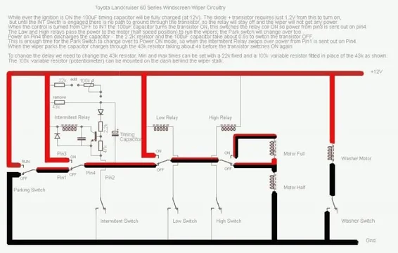
The wiper stalk holds 2 switches – a simple ON-OFF for the washer and a four position OFF-INT-LOW-HIGH switch for the wiper motor. There are 3 relays between the switches and the wiper motor, one controlled by each of the INT-LOW-HIGH switch positions.
The WASHER switch directly connects the powered Washer motor to 0V to operate.
The PARK switch (inside the wiper motor gear housing) provides +12V power to the LOW and INT relays OFF positions while the wiper blades are away from the Park position. At Park it switches not just off, but connects the INT relay normally closed contact to 0V. This connection to 0V greatly simplifies the electronics required for the intermittent delay circuit.
The INT and LOW relays pass the state of the PARK switch when the switches are OFF or +12V when they are ON, on to the HIGH/LOW relay. INT adds a 2-way time delay circuit, when ON it turns its relay ON for 0.5s to start the wiper motor, the PARK switch then provides power for the remainder of the cycle, it then stays off for about 4s before repeating.
The HIGH/LOW relay selects routing power either to half the motor coils (LOW speed) or all of the motor coils (HIGH speed). The High switch turns on both the Low and High relays.

The Intermittent Wiper Circuit –
While ever the ignition is ON a 43,000 ohm resistor and a 100uF bi-polar capacitor are connected between +12V and 0V (through the wiper park system). The capacitor charges towards +12V.
When INT is first selected the power stored on the capacitor immediately flows through a diode and a 2,200ohm resistor to switch on a transistor. (A tiny amount also passes through a 47,000 ohm resistor). When ON the transistor switches the INT relay to send +12V to the wiper motor.
When the relay operates the +12V and 0V connections to the capacitor are reversed via the INT relay AND the PARK switch (the 43,000 ohm resistor acts as an isolator). The voltage on the capacitor drains rapidly through the 2,200 ohm resistor and continues to fall too well below 0V (to about -8V). It takes about 0.5s for the voltage to drop low enough for the transistor to switch off, but by this time the PARK switch is supplying +12V to the OFF position of the relay so the wiper motor continues to run.
After a full wipe cycle the PARK switch will again swap the +12V and 0V connections to the capacitor which will start to charge up from -8V towards +12V. The rate that it charges is controlled by the 43,000 ohm resistor letting +12V in while the diode, 2,200 and 47,000 ohm resistors are letting some leak out. It takes about 4s to rise high enough for the transistor to switch on at which point the Intermittent action repeats.
Modifying the Delay Times –
The 43,000 ohm resistor sets both the time for the PARK switch to take over powering the wiper motor and the time between wipes. We can replace the one, fixed resistor with a combination of a fixed resistor (sets minimum delay time) and a variable resistor (sets maximum delay time) – within reason.
Toyota have chosen conservative values for the timing. In fact we can reduce the value to 10,000 ohms or increase it to 150,000 ohms without creating too short a start time or too long a pause time. A good choice is 22,000 ohms fixed resistor (start time = 0.25s, minimum delay = 1.5s) plus a 100,000 ohm (total = 122,000 ohms) variable resistor (maximum delay = 15s).
Modifying It –
You need –
a) 22,000 ohm resistor, 4 colour code is red, red, orange, gold or 5 colour code is red, red, black, red, gold (one eighths or one quarter watt is more than adequate power handling)
b) 100,000 ohm potentiometer, usually marked B100k (A100k=log type, works too). [Most electronics stores expect the customer to fit a washer and clamp nut to the potentiometer from bulk bins – you need these!]. 16mm diameter is a good fit for the dash switch panels.
c) knob to fit the potentiometer shaft
d) around 1m of insulated hookup wire.
e) hand tools, including a small soldering iron
Step 1 – unplug and remove the INT Relay from beneath the dashboard (for right hand drive it’s the grey box bolted in just above the driver’s left knee, left hand drive = on outer wall to left of driver's knee)
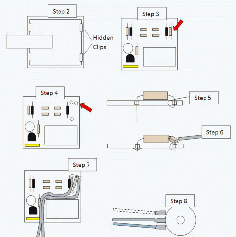
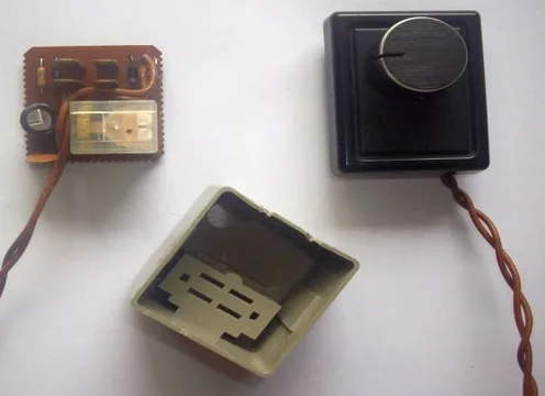
Step 2 – open the box and remove the circuit board – there are 4 plastic clips hidden under the overlapping lid, use a small flat bladed screwdriver to ease these open.
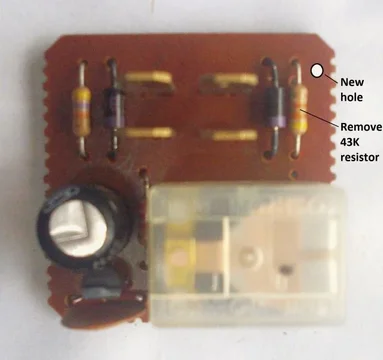
Step 3 – remove the 43,000 ohm resistor (yellow, orange, orange, gold) by melting the solder and pulling out. Clear the holes.
Step 4 – drill a small hole in the top right corner of the board, away from electrical traces.
Step 5 – fit the 22,000 ohm resistor. Put one end into the new hole, wrap the end of the lead wire around the board back to the top, then around itself. Put the other end into the lower hole and pull through until the resistor is flat against the board.
Step 6 – solder the resistor and 2 insulated wires, one to the twisted end of the 22,000 ohm resistor and the other to the empty hole. Trim the leads.
Step 7 – route the wires around the pins and relay (as shown).
Step 8 – solder the potentiometer onto the wires, centre and one end.
Step 9 – Plug in to car and test. If the knob turns the ‘wrong’ way swap the outer wire to the other end on the potentiometer.
Step 10 – glue the wire joints to the circuit board after testing (hot-melt is fine); this prevents the wires touching due to vibration.
Step 11 – cut a slot in the case to allow the wires to emerge then re-assemble the circuit board into the box. Fit the lid
Step 12 – install the relay under the dash and the potentiometer to a dash panel (flatten the lock tab) and fit the knob. If you use a ‘linear’ potentiometer it can be fitted to the back-side of the control stalk, but I’ll leave installation there up to the eager experimenter.

Pictures to follow.
bye.


For about $5 and half an hour's work you can change this to a variable delay continuously adjustable from 1.5 to 15 seconds.
I've wanted to do this for some time and kept hoping that someone (else) would do the experimenting and publish a howto . . .
So I pulled mine apart and reverse engineered the circuit and it turned out to be very easy to do. I've been using it for some time now and it is a vast improvement (at the short end a 2s delay is ideal for drizzle while 12 seconds is great for fog).
Modifying the Toyota Landcruiser 60 Series Intermittent Wiper Circuit
Skip down to 'Modifying It' if you don’t need to know how it works . . .
Overview –
The wiper stalk holds 2 switches – a simple ON-OFF for the washer and a four position OFF-INT-LOW-HIGH switch for the wiper motor. There are 3 relays between the switches and the wiper motor, one controlled by each of the INT-LOW-HIGH switch positions.
The WASHER switch directly connects the powered Washer motor to 0V to operate.
The PARK switch (inside the wiper motor gear housing) provides +12V power to the LOW and INT relays OFF positions while the wiper blades are away from the Park position. At Park it switches not just off, but connects the INT relay normally closed contact to 0V. This connection to 0V greatly simplifies the electronics required for the intermittent delay circuit.
The INT and LOW relays pass the state of the PARK switch when the switches are OFF or +12V when they are ON, on to the HIGH/LOW relay. INT adds a 2-way time delay circuit, when ON it turns its relay ON for 0.5s to start the wiper motor, the PARK switch then provides power for the remainder of the cycle, it then stays off for about 4s before repeating.
The HIGH/LOW relay selects routing power either to half the motor coils (LOW speed) or all of the motor coils (HIGH speed). The High switch turns on both the Low and High relays.

The Intermittent Wiper Circuit –
While ever the ignition is ON a 43,000 ohm resistor and a 100uF bi-polar capacitor are connected between +12V and 0V (through the wiper park system). The capacitor charges towards +12V.
When INT is first selected the power stored on the capacitor immediately flows through a diode and a 2,200ohm resistor to switch on a transistor. (A tiny amount also passes through a 47,000 ohm resistor). When ON the transistor switches the INT relay to send +12V to the wiper motor.
When the relay operates the +12V and 0V connections to the capacitor are reversed via the INT relay AND the PARK switch (the 43,000 ohm resistor acts as an isolator). The voltage on the capacitor drains rapidly through the 2,200 ohm resistor and continues to fall too well below 0V (to about -8V). It takes about 0.5s for the voltage to drop low enough for the transistor to switch off, but by this time the PARK switch is supplying +12V to the OFF position of the relay so the wiper motor continues to run.
After a full wipe cycle the PARK switch will again swap the +12V and 0V connections to the capacitor which will start to charge up from -8V towards +12V. The rate that it charges is controlled by the 43,000 ohm resistor letting +12V in while the diode, 2,200 and 47,000 ohm resistors are letting some leak out. It takes about 4s to rise high enough for the transistor to switch on at which point the Intermittent action repeats.
Modifying the Delay Times –
The 43,000 ohm resistor sets both the time for the PARK switch to take over powering the wiper motor and the time between wipes. We can replace the one, fixed resistor with a combination of a fixed resistor (sets minimum delay time) and a variable resistor (sets maximum delay time) – within reason.
Toyota have chosen conservative values for the timing. In fact we can reduce the value to 10,000 ohms or increase it to 150,000 ohms without creating too short a start time or too long a pause time. A good choice is 22,000 ohms fixed resistor (start time = 0.25s, minimum delay = 1.5s) plus a 100,000 ohm (total = 122,000 ohms) variable resistor (maximum delay = 15s).
Modifying It –
You need –
a) 22,000 ohm resistor, 4 colour code is red, red, orange, gold or 5 colour code is red, red, black, red, gold (one eighths or one quarter watt is more than adequate power handling)
b) 100,000 ohm potentiometer, usually marked B100k (A100k=log type, works too). [Most electronics stores expect the customer to fit a washer and clamp nut to the potentiometer from bulk bins – you need these!]. 16mm diameter is a good fit for the dash switch panels.
c) knob to fit the potentiometer shaft
d) around 1m of insulated hookup wire.
e) hand tools, including a small soldering iron
Step 1 – unplug and remove the INT Relay from beneath the dashboard (for right hand drive it’s the grey box bolted in just above the driver’s left knee, left hand drive = on outer wall to left of driver's knee)
Step 2 – open the box and remove the circuit board – there are 4 plastic clips hidden under the overlapping lid, use a small flat bladed screwdriver to ease these open.
Step 3 – remove the 43,000 ohm resistor (yellow, orange, orange, gold) by melting the solder and pulling out. Clear the holes.
Step 4 – drill a small hole in the top right corner of the board, away from electrical traces.
Step 5 – fit the 22,000 ohm resistor. Put one end into the new hole, wrap the end of the lead wire around the board back to the top, then around itself. Put the other end into the lower hole and pull through until the resistor is flat against the board.
Step 6 – solder the resistor and 2 insulated wires, one to the twisted end of the 22,000 ohm resistor and the other to the empty hole. Trim the leads.
Step 7 – route the wires around the pins and relay (as shown).
Step 8 – solder the potentiometer onto the wires, centre and one end.
Step 9 – Plug in to car and test. If the knob turns the ‘wrong’ way swap the outer wire to the other end on the potentiometer.
Step 10 – glue the wire joints to the circuit board after testing (hot-melt is fine); this prevents the wires touching due to vibration.
Step 11 – cut a slot in the case to allow the wires to emerge then re-assemble the circuit board into the box. Fit the lid
Step 12 – install the relay under the dash and the potentiometer to a dash panel (flatten the lock tab) and fit the knob. If you use a ‘linear’ potentiometer it can be fitted to the back-side of the control stalk, but I’ll leave installation there up to the eager experimenter.

Pictures to follow.
bye.
Last edited:


