
My '92 350TBI conversion into '88 FJ62 was "completed" almost exactly this time last year. I have had it wired up and running for barely a year now and have been slowly trying to "clean up" some of the circuitry. It's been a daily driver though since I first got exhaust put on it.
So I pulled into the driveway this afternoon after sweating it out for a few miles in traffic watching my voltmeter drain down to the number 8...opened the hood and checked the battery and alternator with a voltmeter and realized both were in bad shape. On top of that, I realized that my fusible link going to the alternator (heavy gauge white wires attached to stud on alternator) was also worn and looked like it had taken some heat. (It was barely attached to the battery which I am assuming is at least half my problem)
At this point I'm looking for some advice on wiring up the alternator correctly before I try to burn up another one or worse yet cause a movie-like explosion. (BTW, I have the FSM wiring diagram for the Toyota and a cr&ptastic Chilton's manual for the chevy.)
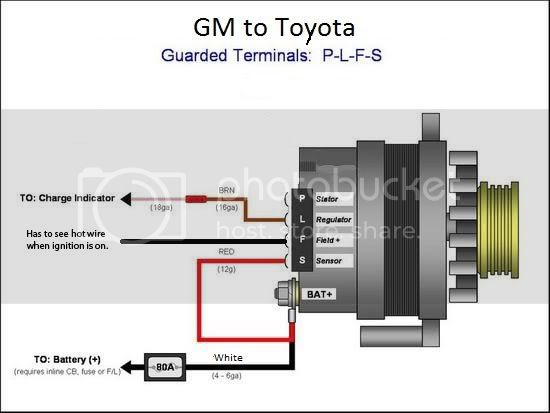
GM alternator has:
-large stud/nut on back
-pig tail with:
-red wire -12 gauge (Chilton diagram shows it going to bat. w/ fusible link)
-brown wire -14 gauge (can't tell exactly what it should go to...ignition switch?)
-black wire -14gauge (Chilton's is not very helpful for this one either)
Toyota harness has:
-two heavy gauge white wires to an eyelet (Should go to the stud on Alt I presume?)
-white wire ~12 gauge (*this wire does not show up in the wiring diagram?)
-white/yellow wire ~14 gauge (to 10 amp fuse & ignition main relay)
-black/yellow wire ~16 gauge (to 7.5 amp fuse & charge light relay)
Like I said before, I've had it running for a year now so if noone has any input I'll just keep it the way it is and see what blows up next. But if anyone were to have some advice I'd be all ears and very appreciative. Thanks in advance...
-Darin
So I pulled into the driveway this afternoon after sweating it out for a few miles in traffic watching my voltmeter drain down to the number 8...opened the hood and checked the battery and alternator with a voltmeter and realized both were in bad shape. On top of that, I realized that my fusible link going to the alternator (heavy gauge white wires attached to stud on alternator) was also worn and looked like it had taken some heat. (It was barely attached to the battery which I am assuming is at least half my problem)
At this point I'm looking for some advice on wiring up the alternator correctly before I try to burn up another one or worse yet cause a movie-like explosion. (BTW, I have the FSM wiring diagram for the Toyota and a cr&ptastic Chilton's manual for the chevy.)
GM alternator has:
-large stud/nut on back
-pig tail with:
-red wire -12 gauge (Chilton diagram shows it going to bat. w/ fusible link)
-brown wire -14 gauge (can't tell exactly what it should go to...ignition switch?)
-black wire -14gauge (Chilton's is not very helpful for this one either)
Toyota harness has:
-two heavy gauge white wires to an eyelet (Should go to the stud on Alt I presume?)
-white wire ~12 gauge (*this wire does not show up in the wiring diagram?)
-white/yellow wire ~14 gauge (to 10 amp fuse & ignition main relay)
-black/yellow wire ~16 gauge (to 7.5 amp fuse & charge light relay)
Like I said before, I've had it running for a year now so if noone has any input I'll just keep it the way it is and see what blows up next. But if anyone were to have some advice I'd be all ears and very appreciative. Thanks in advance...
-Darin

")

