Temp sensor wiring 78 (1 Viewer)

This site may earn a commission from merchant affiliate
links, including eBay, Amazon, Skimlinks, and others.

Catching Neutral

GOLD Star
Joined
Jul 19, 2011
Threads
49
Messages
1,611
Location
FL
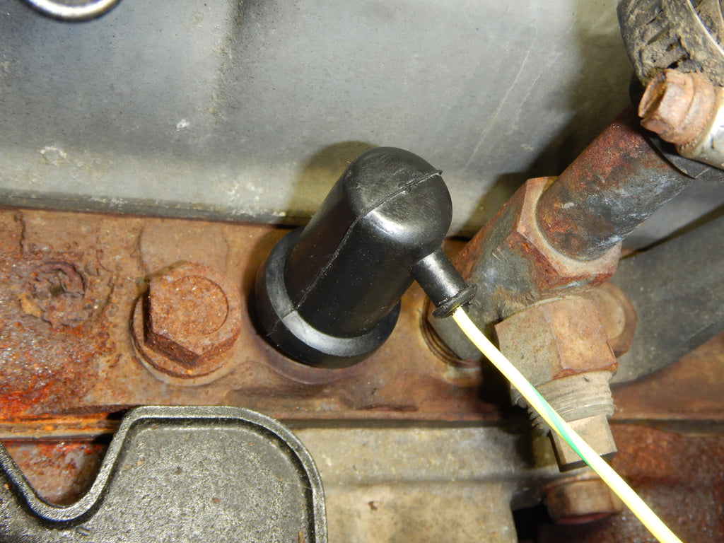
Ok guys. PO has installed a gauge cluster in the location where the radio blank belongs. I would like to get rid of this cluster And the after market PVC temp sensor. Therefore I would like to reconnect the original temp sensor. It looks like both temp sensors are close together minus the wiring. (Circled in red) Is the green connecter( circled in yellow) in the photo where temp sensor needs to be hooked up?

3425D2E8-DC3E-4F60-B605-6F7A348A275B.jpeg


CD34183F-EB99-4282-B42C-C41CC6CCF080.jpeg


B3CABF59-6899-497A-9437-A252354FCC2E.jpeg
 
I'll take a photo of mine if there is enough light (cloudy/rainy today).

Yours does not look stock to me - looks like someone plumbed two sensors into a single location on the head? PCV hose is in the way in your photo.
 

On another subject concerning your photo, the valve cover vent hose to the air cleaner may need addressing. If you haven't done so, it might be a good idea to order the Ventilation Hose #3, OEM part number 90910-05101.
 
1911, you are correct. Both sensors are plumbed into a single spot with the central portion being directly behind PCV hose in the photo. I’ll get a better photo ASAP.
Thank you GA for the part number as that hose as well as most of the others are on the to do list.
 
Fortunately, your engine head has plenty of holes for sending units. I would remove and test both those OEM sensors (or what appear to be OEM) and reconnect the dashboard temp gauge.

Getting rid of that PVC abomination and gauges makes sense. You could always buy a set of two, tasteful aftermarket gauges (temp and mechanical oil pressure) and mount them under the dash. Then, install the temp sensor in the head, where it belongs. SOR.com should have a diagram showing the proper location of the OEM head-installed temp sensor. Oil pressure can be tee-d in at the OEM sender location.
 
Thank you Steve. I would like to reconnect the OEM temp gauge. The OEM Fuel and Oil pressure gauges currently function properly. The question—— Is the green connector (circled in yellow in the photo) responsible for the temp sensor?
 
Uh.... this might muddy the issue rather than clear it but - - -
345DEBE1-16AB-4680-AF9B-8FE9031CD5B2.jpeg

My truck’s an ‘82 so maybe a little different - I just replaced the temp sensor - there’s just a one wire connection on mine but maybe if your rig is a CA version, it could be set up for coolant temp and something with emissions due to that dual connector! You should contact Coolerman to find out for sure!
 
I was able to peel back the casing and there is a yellow wire and a red wire. Yellow I believe is for temp gauge and red for water thermo switch (California models only). Still not sure what to make of the way 2 temp sensors are Y Ed in together

02BD3036-A2D4-4D9A-8B81-37C647C784AD.jpeg


7B901BBB-A687-4EF6-8999-64827DE09277.jpeg


0D9AAF60-C8D2-4C75-A310-D4748D20DDFE.jpeg
 
My ‘78 has two of those green connectors... one for carb cooling fan, the other for the carb idle solenoid. Neither are near the firewall, like yours.

My 12/79 is the same as Danny describes.

Here is a photo of my water temp sender, though it is not stock (I'm using an aftermarket Autometer temp gauge). Even though it is not stock, it still hooks up like stock - with a single wire, not connected to a dual-blade green connector. Like the schematic that Danny posted, stock is also a single-wire connection.

IMG_1409[1].JPG


IMG_1409[1].JPG
 
I'll take a photo of mine if there is enough light (cloudy/rainy today).

Yours does not look stock to me - looks like someone plumbed two sensors into a single location on the head? PCV hose is in the way in your photo.


Here are some good close up's of my past temp gauge repairs and upgrades

- YES the Yellow wire or Yellow w / green tracer is for the gauge in the dash

- there should be a 2nd Sensor Union Port behind Your carb on your California

please see the link below for what the Sensor union looks like

- i have never seen a Y or T splutter like you have ?

- see the Hose Bib in link below for reference

- you should have a DELETE caps plugs for extra coolant ports

- make sure u are certain on what is a Head Bolt and what is a Coolant Delete plug port , Sounds Phunny , but my buddy pulled his head bolts years ago
trying to do a similar fix ...... my my , ......


DSCN7468.JPG
DSCN7471.JPG
DSCN7475.JPG


Thank you Toyota Matt.
Looks like I have my marching orders
Do you happen to happen to have the other side of this connector?

EF3C9394-A31D-4598-9798-70354493CFB1.jpeg
 
Does this look like a Second sensor Union Port

F1F1505B-1DDE-43D8-B2E4-16E7C3F35FB6.jpeg
 
Looks like PO considered fixing this issue as I found this in my box of parts that came with vehicle.
Any idea what this sensor is?

715AB657-D617-438A-A043-5FD3EB86523C.jpeg


62E199D3-4B26-4F7B-B69B-BCA3795958F5.jpeg
 
Thanks to all for your input. No telling what the PO had in mind for this sensor. I think i have a plan in place to get this temp gauge fixed however out of town for a while, it will be the end of March before I get some garage time. Parts will be here when I get back
 
Thank you Toyota Matt.
Looks like I have my marching orders
Do you happen to happen to have the other side of this connector?

View attachment 2234762


Ok , ................so here we go .....

- Sorry for all the Color Code's text , but i feel this some what complex Mess you have going on is best and SAFEST explained in plain Color Codes ......

and the Photo in the Tan FSM , how ever Poor and grainy , gets the job done
well showing you the Big picture of what all you are having as a Job Scope total


- Your RED Labeled Coolant port has the recessed Hex Plug in it Now , it's where Your NEW OEM Hose Bib / Union Joint will be going , closest to the fire wall .........

need to first drain your coolant , and then remove that AFTERMARKET plug with Care , take your time and NO heat or a Torch , BAD idea .....
.


- Then , the BLUE, labeled Coolant PORT is where u first need to Remove that
Gerry Rig PO " Thing " , Carefully once again , and then install a New OEM
Short Temp Sensor Union , like i showed above in the reference photos , U will also need a OEM TOYOTA Temp. Sender sensor , from the Dealer , or i can help you on that ,
NO PEP BOYS parts here ! for that location !


- The Yellow marked Plug in the Photo is a Delete Plug , U may expect another
recessed hex plug , or something else ? Please post a good close up photo of the Yellow Therm o Sensor Port Location , U may need another Sensor Union or .........?
never the less thats where the 2nd sensor goes for therm o- gauge sender .......


- I would Expect you Might Just have to Remove Your Valve Cover First , to remove the ODD welded Thing the PO's installed ? 🤔

and it will be required to install your NEW OEM Hose Bib Joint Union ......too

no clearance to rotate it in ............


DSCN0761_LI.jpg


DSCN0760.JPG


oh ,

and yes i have plenty of 2 Pin Sealed OEM Connectors , terminals and rubber plugs in stock , for your 2 pin sealed green one hanging there , to mate up with Proper by the Book ,

i can set you up with some nice long color code tracer stripe
Leeds if you need them , Wrapped in Flame Proof Wire Loom Just like , when she was new , rolling out of Pant A11 back in the day ...........:D

do not estimate wires melting on your manifold ! i can and does happen


You can feel free to shoot me a Pm with any Questions you have ,

the most difficult part i think , is gonna, be the 2 aftermarket Delete plugs removal , but nothing a long steady 1/2" breaker bar can't take care of ......


hope this helps ................


kindly matt
 

Users who are viewing this thread

Back
Top Bottom