As an update for those researching this, I don't think the solution is quite as clear as described above because the dash switch is a momentary switch and only provides power while depressed.
I am installing an aftermarket power antenna (Metra, like most people) and wired it up as described in post #27.
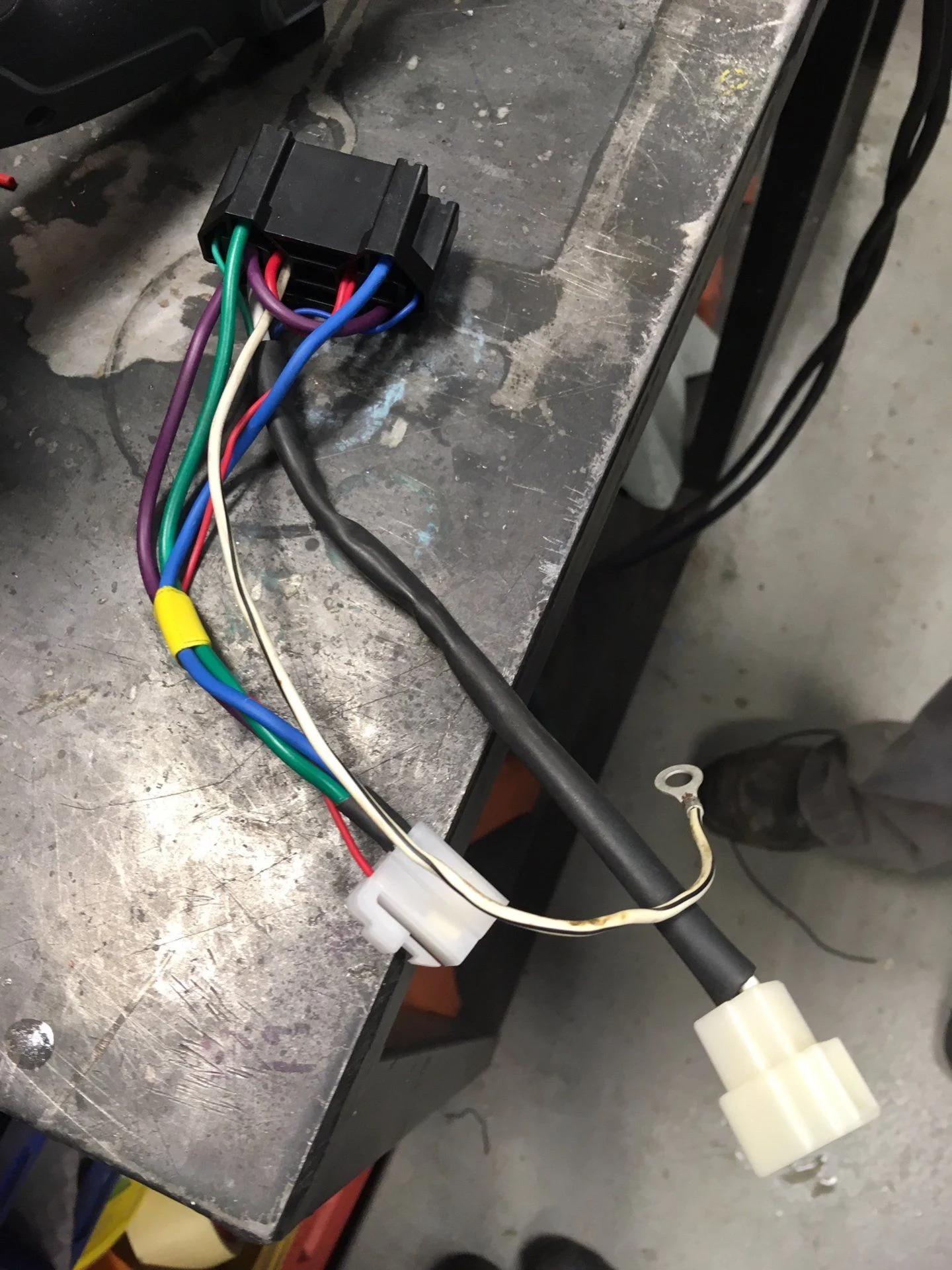
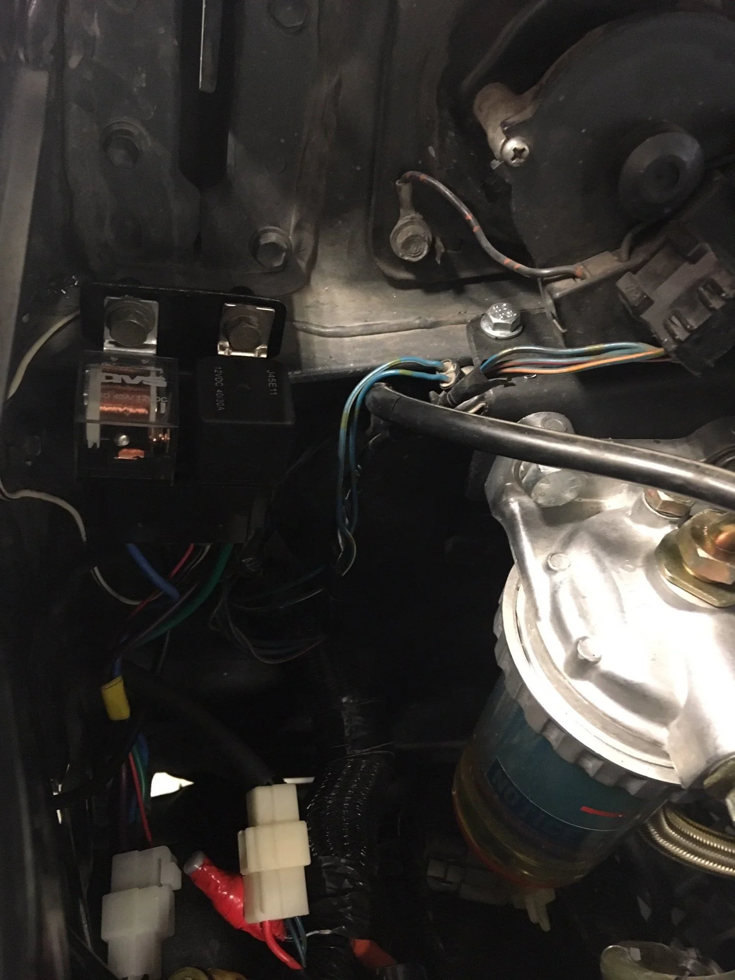
Connected the trigger wire for new antenna directly to the harness (blue + blue/white wires) in the engine compartment that plugged in to the old antenna. IIRC, I connected trigger wire from new antenna to the solid blue wire in the original harness. The new antenna will go up when you press up on the dash switch, but only stays up as long as the dash switch is held in the up position. As soon as you let go of the dash switch it disengages and the antenna will retract.
Don't have a solution yet, but would be interested to hear any ideas. I could always connect the antenna trigger wire to the radio, but am really interested in retaining the factory functionality where you can control up/down manually. I also suppose an on/off switch could be used in place of the original dash switch, but I don't want to go hacking in to the original wiring.
I have one more suggestion if you have not already figured it out. Honestly, I wish I could have remembered this option before.
The use a of a single diode, should have taken care of this problem long ago. Providing that it is NOT one of those cheap antennas that don't have actual mechanical "Limit Switches" and relay. If it has a cheap control board, that measures resistance when it is fully extended or fully retracted, then a diode will/might work, but there is trick to it. You have to bump it up, then press down.
Furthermore if you want to use the original switch and have a cheap antenna, then using only 2 relays the same trick will have to be done. To not have to do the trick make the two relays latching.
If you are lucky and have an antenna that has actual mechanical limits & a relay to control direction, then all you need is a Diode. Diagram below.
Link to diagram, Leave message with request. Without message saying what forum and link to forum requests will be denied.
**********************************************************************************************************************************************
If your antenna is a cheap one that only has a cheap control board (like this one I took apart).
The mechanical limits should be in here. So watch out for or look here to see how you will need to wire. I am guessing that it is cheaper to not retool the factory or the manufactures want you to still buy from them, so they keep it there to seem as it still has better quality parts.
This board is the only thing inside for control. It measures resistance to stop the motor when it is fully retracted or extended.
If you want to use the original switch you will need to use two relays. The three antennas I tested, with the control board, all kept failing to extend or retract unless there was power already. Power needs to be there before so the board can be triggered. If an in depth explanation is needed I will think about writing it up.
This diagram is if you have one with the cheap boards and you want to use the original switch.
Ignition switch power is the source of power for the antenna motor. Same as most Vehicles.
Center relay provides power to extend.
When the Up is pressed, the Left relay latches through the Right relay. Power is kept on to keep the antenna extended. Like most vehicles.
When the Down is pressed, the Right relay will turn on and will Unlatch the Left relay.
Link to diagram, Leave message with request. Without message saying what forum and link to forum requests will be denied.
Apologies I was never notified there were replies.