
After upgrading to slightly larger tires I decided I wanted to have the most accurate speedometer I could. I searched MUD for write-ups on the speedo correction boxes and found some good info but no definitive step-by-step how to. After reading these two threads:
https://forum.ih8mud.com/100-series...alling-generic-marks4wd-speed-calibrator.html
https://forum.ih8mud.com/100-series-cruisers/211990-installed-superlift-speed-sensor-calibrator.html
I had the confidence that it wouldn’t be too hard, so I made a quick call to Slee and the Marks Speedometer Correction Box was on its way.
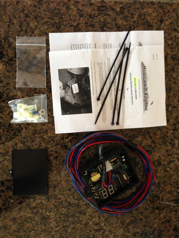
The kit comes with the programmable box (with plenty of wire), directions, and some wiring connectors.
http://www.dominicsmith.com/100_Series_Speedo_Correction_files/Media/IMG_2591/IMG_2591.jpg
There are basically 5 steps once you purchase the unit.
1. Remove the glove box.
2. Locate correct wires and make connections and then test that you’re getting power, etc.
3. Program the box and road test.
4. Make connections permanent.
5. Replace glove box.
STEP 1: GLOVE BOX REMOVAL
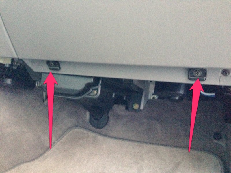
The first step was to remove the glove box. Start by removing the two screws at the bottom which loosens the entire assembly...
http://www.dominicsmith.com/100_Series_Speedo_Correction_files/Media/IMG_0064/IMG_0064.jpg
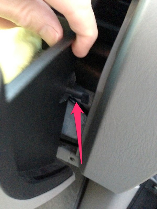
Slide the glove box to the left and pull out on the right side being sure to clear the tab on the right...
http://www.dominicsmith.com/100_Series_Speedo_Correction_files/Media/IMG_0063/IMG_0063.jpg
Next I had to disconnect the lanyard that attaches to the left side of the glove box. This tends to retract up into the dash and may be hard to find once you need to re-assemble. Now the glove box is free to place out of the way.
http://www.dominicsmith.com/100_Series_Speedo_Correction_files/Media/IMG_0065/IMG_0065.jpg
STEP 2: WIRING (Disconnect battery ground)
Speedo Box wires-
Red (PWR) to switched power source
Black (GRND) to ground
Blue (OUT) to R-G to speedo
Brown (IN) to R-G from loom
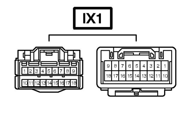
Next was locating the appropriate wires to attach the speedo box to the stock wiring harness. The wiring diagram shows the Vehicle Speed Sensor (VSS) passing through connector IX1 before heading to the speedometer. It’s shown as PIN 6 on IX1 and is R-G (Red w/ Green). This is the wire to tap into with the Blue and Brown wires from Marks Speedo Box. From the 2004 EWD...
http://www.dominicsmith.com/100_Ser... AM/Screen Shot 2013-02-27 at 11.31.03 AM.jpg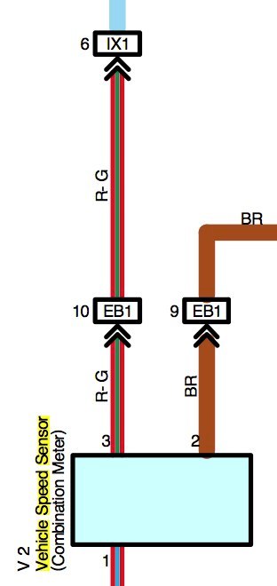
http://www.dominicsmith.com/100_Series_Speedo_Correction_files/Media/IX1/IX1.jpg
On my 2004 it was found just to the left of the ECM at the bottom of a cluster of plugs (not plugged into the ECM)...
http://www.dominicsmith.com/100_Series_Speedo_Correction_files/Media/IMG_0078/IMG_0078.jpg
It has a push-in fitting at the back of the plug holding it in place, just pull it towards you off its mounting location. This is what it looks like:
http://www.dominicsmith.com/100_Series_Speedo_Correction_files/Media/IMG_0067/IMG_0067.jpg
Now you can unplug it and CAREFULLY use a razor to cut back the wiring protector to gain better access to the wiring loom...
http://www.dominicsmith.com/100_Series_Speedo_Correction_files/Media/IMG_2569/IMG_2569.jpg
Next confirm you have the right plug. The female side has all Sky Blue wires and the male side you're tapping into has R-G in both PIN 6 and PIN 7. I marked PIN 6 with tape to be sure I didn’t mix up the two...
http://www.dominicsmith.com/100_Series_Speedo_Correction_files/Media/IMG_2570/IMG_2570.jpg
I decided to keep the speedo box out of the glove box because I keep things in there and felt like the toggle had potential to get tripped in there. I opted to Velcro it up under the footwell beneath the glove box where there was room but would not interfere with passenger foot space. I routed the speedo box wires up from that location to the area behind the glove box for the connections...
http://www.dominicsmith.com/100_Series_Speedo_Correction_files/Media/IMG_2600/IMG_2600.jpg
Then I cut the PIN 6 R-G wire and connected the brown wire to the R-G wire heading into the loom and the blue wire to the R-G wire going into the rear of the plug. I made temporary wire nut connections for the testing process...
http://www.dominicsmith.com/100_Series_Speedo_Correction_files/Media/IMG_2602/IMG_2602.jpg
http://www.dominicsmith.com/100_Series_Speedo_Correction_files/Media/IMG_2603/IMG_2603.jpg
Now I took the recommendation of jhrrld and tapped into the antenna relay wiring (A30) located nearby. There are certainly other wires to choose from but I decided to stick with something that had been confirmed to work...
http://www.dominicsmith.com/100_Series_Speedo_Correction_files/Media/IMG_0077/IMG_0077.jpg
Connecting to “power” with the red wire, I used PIN 7 (B-W) and “ground” I used PIN 5 (W-B).
http://www.dominicsmith.com/100_Series_Speedo_Correction_files/Media/A30/A30.jpg
PIN 7 is switched ON, not ACC so be sure to note that when testing. There’s not a lot of room in that area so making the connections may be difficult. Again I marked each wire with tape to be sure I was connecting to the appropriate wire...
http://www.dominicsmith.com/100_Series_Speedo_Correction_files/Media/IMG_0070/IMG_0070.jpg
The white tap-in connectors supplied were basically worthless as they aren’t small enough for the wires I chose to tap into. Don't waste your time trying this...
http://www.dominicsmith.com/100_Series_Speedo_Correction_files/Media/IMG_2601/IMG_2601.jpg
I eventually stripped a small section of each factory wire (without cutting) and wrapped the speedo box wire tightly around them then covered them in tape until testing was complete.
http://www.dominicsmith.com/100_Series_Speedo_Correction_files/Media/IMG_2606/IMG_2606.jpg
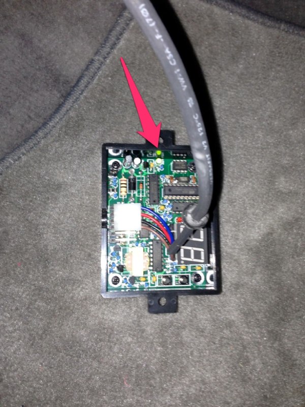
Then I re-connected the battery and checked that I was getting 12v to the red wire and confirmed that the green LED came on inside the speedo box when the key was turned to ON. Leave the back cover off for now...

https://forum.ih8mud.com/100-series...alling-generic-marks4wd-speed-calibrator.html
https://forum.ih8mud.com/100-series-cruisers/211990-installed-superlift-speed-sensor-calibrator.html
I had the confidence that it wouldn’t be too hard, so I made a quick call to Slee and the Marks Speedometer Correction Box was on its way.
The kit comes with the programmable box (with plenty of wire), directions, and some wiring connectors.
http://www.dominicsmith.com/100_Series_Speedo_Correction_files/Media/IMG_2591/IMG_2591.jpg
There are basically 5 steps once you purchase the unit.
1. Remove the glove box.
2. Locate correct wires and make connections and then test that you’re getting power, etc.
3. Program the box and road test.
4. Make connections permanent.
5. Replace glove box.
STEP 1: GLOVE BOX REMOVAL
The first step was to remove the glove box. Start by removing the two screws at the bottom which loosens the entire assembly...
http://www.dominicsmith.com/100_Series_Speedo_Correction_files/Media/IMG_0064/IMG_0064.jpg
Slide the glove box to the left and pull out on the right side being sure to clear the tab on the right...
http://www.dominicsmith.com/100_Series_Speedo_Correction_files/Media/IMG_0063/IMG_0063.jpg
Next I had to disconnect the lanyard that attaches to the left side of the glove box. This tends to retract up into the dash and may be hard to find once you need to re-assemble. Now the glove box is free to place out of the way.
http://www.dominicsmith.com/100_Series_Speedo_Correction_files/Media/IMG_0065/IMG_0065.jpg

STEP 2: WIRING (Disconnect battery ground)
Speedo Box wires-
Red (PWR) to switched power source
Black (GRND) to ground
Blue (OUT) to R-G to speedo
Brown (IN) to R-G from loom
Next was locating the appropriate wires to attach the speedo box to the stock wiring harness. The wiring diagram shows the Vehicle Speed Sensor (VSS) passing through connector IX1 before heading to the speedometer. It’s shown as PIN 6 on IX1 and is R-G (Red w/ Green). This is the wire to tap into with the Blue and Brown wires from Marks Speedo Box. From the 2004 EWD...
http://www.dominicsmith.com/100_Ser... AM/Screen Shot 2013-02-27 at 11.31.03 AM.jpg

http://www.dominicsmith.com/100_Series_Speedo_Correction_files/Media/IX1/IX1.jpg
On my 2004 it was found just to the left of the ECM at the bottom of a cluster of plugs (not plugged into the ECM)...
http://www.dominicsmith.com/100_Series_Speedo_Correction_files/Media/IMG_0078/IMG_0078.jpg

It has a push-in fitting at the back of the plug holding it in place, just pull it towards you off its mounting location. This is what it looks like:
http://www.dominicsmith.com/100_Series_Speedo_Correction_files/Media/IMG_0067/IMG_0067.jpg

Now you can unplug it and CAREFULLY use a razor to cut back the wiring protector to gain better access to the wiring loom...
http://www.dominicsmith.com/100_Series_Speedo_Correction_files/Media/IMG_2569/IMG_2569.jpg

Next confirm you have the right plug. The female side has all Sky Blue wires and the male side you're tapping into has R-G in both PIN 6 and PIN 7. I marked PIN 6 with tape to be sure I didn’t mix up the two...
http://www.dominicsmith.com/100_Series_Speedo_Correction_files/Media/IMG_2570/IMG_2570.jpg

I decided to keep the speedo box out of the glove box because I keep things in there and felt like the toggle had potential to get tripped in there. I opted to Velcro it up under the footwell beneath the glove box where there was room but would not interfere with passenger foot space. I routed the speedo box wires up from that location to the area behind the glove box for the connections...
http://www.dominicsmith.com/100_Series_Speedo_Correction_files/Media/IMG_2600/IMG_2600.jpg

Then I cut the PIN 6 R-G wire and connected the brown wire to the R-G wire heading into the loom and the blue wire to the R-G wire going into the rear of the plug. I made temporary wire nut connections for the testing process...
http://www.dominicsmith.com/100_Series_Speedo_Correction_files/Media/IMG_2602/IMG_2602.jpg

http://www.dominicsmith.com/100_Series_Speedo_Correction_files/Media/IMG_2603/IMG_2603.jpg

Now I took the recommendation of jhrrld and tapped into the antenna relay wiring (A30) located nearby. There are certainly other wires to choose from but I decided to stick with something that had been confirmed to work...
http://www.dominicsmith.com/100_Series_Speedo_Correction_files/Media/IMG_0077/IMG_0077.jpg

Connecting to “power” with the red wire, I used PIN 7 (B-W) and “ground” I used PIN 5 (W-B).
http://www.dominicsmith.com/100_Series_Speedo_Correction_files/Media/A30/A30.jpg

PIN 7 is switched ON, not ACC so be sure to note that when testing. There’s not a lot of room in that area so making the connections may be difficult. Again I marked each wire with tape to be sure I was connecting to the appropriate wire...
http://www.dominicsmith.com/100_Series_Speedo_Correction_files/Media/IMG_0070/IMG_0070.jpg

The white tap-in connectors supplied were basically worthless as they aren’t small enough for the wires I chose to tap into. Don't waste your time trying this...
http://www.dominicsmith.com/100_Series_Speedo_Correction_files/Media/IMG_2601/IMG_2601.jpg

I eventually stripped a small section of each factory wire (without cutting) and wrapped the speedo box wire tightly around them then covered them in tape until testing was complete.
http://www.dominicsmith.com/100_Series_Speedo_Correction_files/Media/IMG_2606/IMG_2606.jpg

Then I re-connected the battery and checked that I was getting 12v to the red wire and confirmed that the green LED came on inside the speedo box when the key was turned to ON. Leave the back cover off for now...
Now you're ready to program and test...


 or (Stupid character smiley faces!!!)


")