OK, I've been reading on here for a couple weeks about installing a Scion head unit into my '96 LX. Obviously, installing a Scion HU into a LC seems to be very simple--plug and play. But it's a little more complicated for the LX. I'd like to compile a definitive list of parts and instructions to complete this swap, but I'll need help from the experts, please!!!
There have been a couple good threads...but nothing "definitive". This seems to be the best one: https://forum.ih8mud.com/80-series-tech/218369-how-i-installed-scion-1808-hu-into-my-lx-450-a.html
There is also some good wiring information in this thread: https://forum.ih8mud.com/80-series-tech/72688-1997-lx-450-radio-install-help.html
After contributions from many members and some editing to compile information the following is the complete write-up.
So, what all is needed?
1.) Scion HU of your choice -- but make sure it's iPod compatible if you want that feature (I chose the T1806 because you can change the display color)
2.) Scion iPod harness (SC12235, available on eBay for $15)
3.) Toyota wiring harness (Metra 70-1761, available at Best Buy for $20)
4.) Toyota factory radio harness (Mobilistics WH-77, available from Mobilistics for about $4)
5.) Approximately 15' of 18 gauge wire
6.) Approximately 25 butt connectors (I got the butt connectors with shrink wrap already on them, pretty slick!)
7.) Two splice connectors
Installation steps:
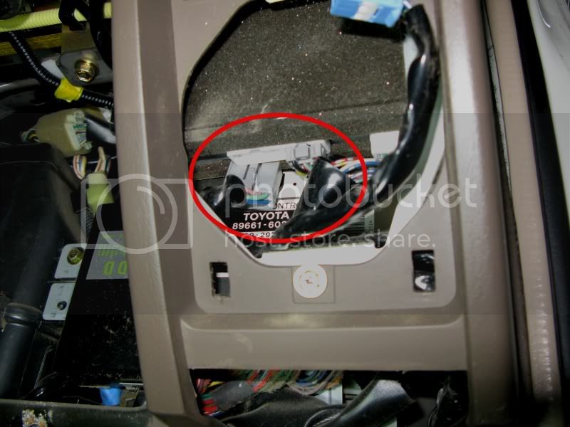
A.) Remove the factory radio by removing the ash tray and pocket above the head unit. There are four screws that have to be removed in those areas then carefully pop out the bezel's friction clips. I also disconnected all the switch connectors (hazard, CDL, antenna, etc.) and the HVAC connections but I didn't fully remove the bezel from the truck. Remove the four screws in the brackets holding the head unit to the dash assembly. Once you remove the factory radio, those connectors are abandoned and not reused--except for the antenna. That cable will be reused.
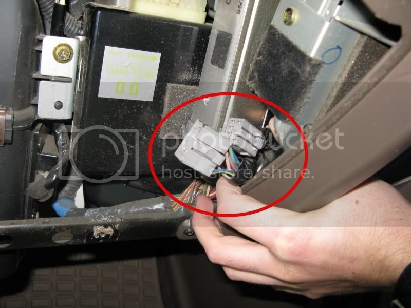
B.) Remove the glove box--there are two screws at the bottom. Remove the tweeter next to the glove box--there is one screw and then the whole assembly can be removed after disconnecting the wire harness to the tweeter. Disconnect both of the gray connections on the factory amp behind the glove box/tweeter area. The new Metra wiring harness (#3 above) connects to these plugs and the factory amp is abandoned.
C.) The new Mobilistics harness (#4 above) connects to the Scion HU.
D.) Wiring connections have to be made between the Metra harness (#3 above) and the Mobilistics harness (#4 above). The combined harness needs to be approximately 24" long to reach from the amp to the HU location.
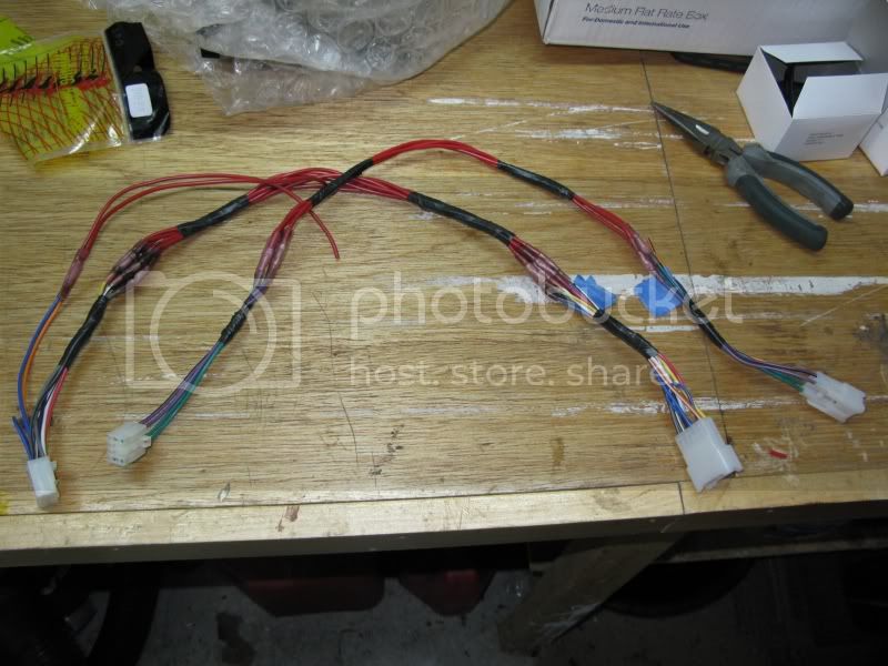
Essentially, all you are doing is extending the factory harness that plugs into the amp over so you can plug it into the Scion HU. The existing harness in the LX is not long enough.
Knorrena and Romer have both provided some insight on how to make the connections between the two harnesses I mentioned in item D above. Some of the wiring information is also taken from Options20002001 in the other thread linked above.
LX__(S15)_____Scion_(R2)
1__FR+________FR+
2__FL+________FL+
3__PWR_(acc)__PWR_(acc)
4__PWR________PWR
5__FR-________FR-
6__FL-________FL-
7__GND________GND
8__X__________PWR ANT
9__X__________X
10_X__________Illum+
(S17)_________(R3)
1__RR+________RR+
2__RL+________RL+
3__RR-________RR-
4__WF+_______Rem._on
5__WF-_______Illum-
6__RL-________RL-
See notes below for the items in red text.
Required harness modifications:
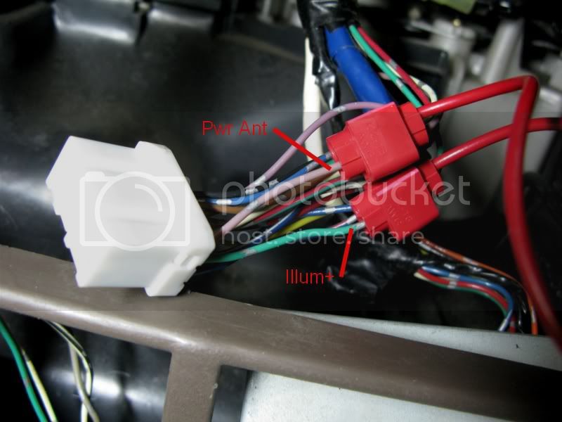
1.) PWR ANT -- On the Scion R2 plug, pin #8 gets spliced into pin #8 (lavendar wire) of the R1 connector that will be abandoned behind the radio.
2.) Illum+ -- On the Scion R2 plug, pin #10 gets spliced into pin #2 (green wire) of the R1 connector that will be abandoned behind the radio.
There are two connectors at the back of the OEM radio--the white 15-pin R1 connector is the one that needs to get spliced into for the PWR ANT and Illum+. This R1 connector is laid out as follows:
R1
1^^2^^3^^4^^^^^^^^^5^^6^^7
8^^9^^^^10^11^12^13^^^14^15
1 = amp turn on; blue
2 = ILL +
3 = ACC; blue/red
4 = Bat +; blue/white
5 = Mute; white
6 = FL; green
7 = FR; blue
8 = ANT turn on
9 = ILL (variable controlled by the dimmer)
10 = Telephone mute; red/green
11 = Power ground; Violet
12 = Signal ground; brown
13 = Beep; black
14 = RL; yellow
15 = RR; red
3.) Rem. On -- This pin is not needed for this install. Apparently the Rem. On was a function for steering wheel controls in the Scions.
4.) Illum- -- This pin is not needed for this install.
This is how the final connections will look:
LX__(S15)_____Scion_(R2)
1__FR+________FR+
2__FL+________FL+
3__PWR_(acc)__PWR_(acc)
4__PWR________PWR
5__FR-________FR-
6__FL-________FL-
7__GND________GND
8__X__________PWR ANT (splice into abandoned harness pin #8, Pwr Ant (lavendar))
9__X__________X
10_X__________Illum+ (splice into abandoned harness pin #2, Illum+ (green))
(S17)_________(R3)
1__RR+________RR+
2__RL+________RL+
3__RR-________RR-
4__WF+_______X
5__WF-_______X
6__RL-________RL-
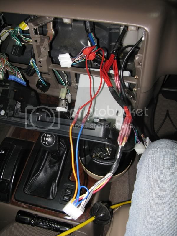
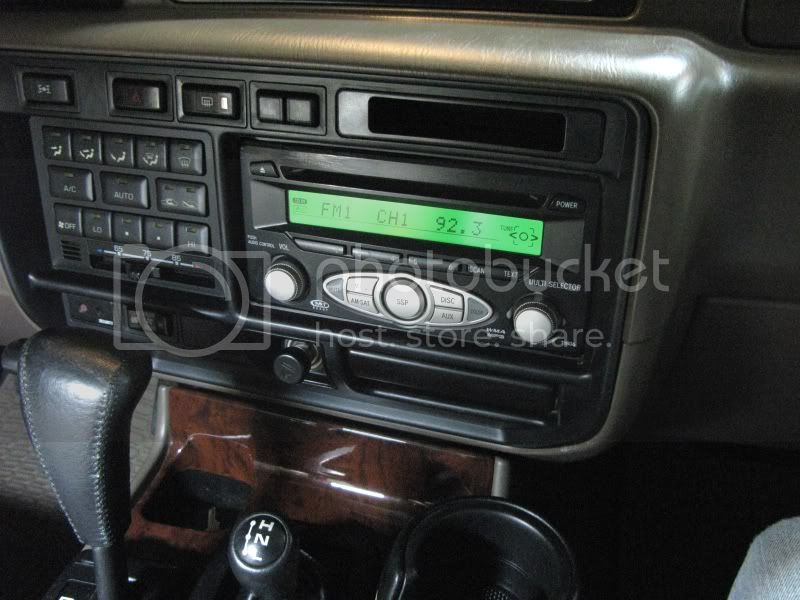
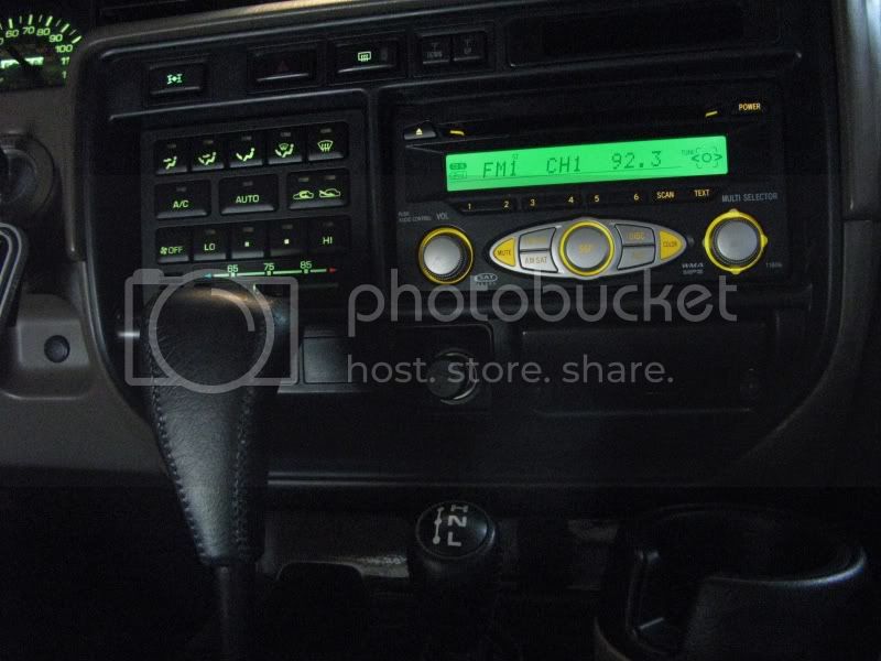
E.) Once you have the wiring done, it's time to put it all back together, but first you'll need to trim the bezel. First, make sure that you've connected both the connectors to the back of the head unit, the antenna cable, and also the iPod connector if you are installing that option. I installed the head unit and then put the bezel up to determine how much material to remove. I found it easiest to use a dremel with a cut off wheel. I also used a small drill bit style tool in the dremel to remove some material from the head unit. This is basically just trial and error, just take it slow and be careful. After all the cutting was done I smoothed it down with a file and some 400 grit sand paper, then I took a lighter to the plastic to get rid of the haze. If you use the heat in short bursts it will give the gloss back to the plastic but won't warp it.
F.) After you trim it to fit, put the screws back in, make all the final connections near the amp, hang the wires out of the way of the glove box, and then install the glove box and tweeter. I left the iPod cable and iPod in the glove box. It keeps it out of the way and you really don't ever need access to it. You can control the iPod through the head unit. You're done!
Lights off:
Lights on:
(...I need new bulbs in the Hazard and Antenna switches...)

Additional data on the connectors for further information/clarification:
The two connectors at the factory amp that we have to disconnect and extend to the new head unit are the S15 and S16. They are laid out as follows:
S15
1^^2^^^^^^^^3^^4
5^^6^^7^^X^^X^^X
1 = FR speaker +; light green
2 = FL speaker +; pink
3 = ACC; gray
4 = Bat +; blue/yellow
5 = FR speaker -; blue
6 = FL speaker -; violet
7 = Ground; brown
S17
1^^^^^^^^2
3^^4^^5^^6
1 = RR speaker +; red
2 = RL speaker +; black
3 = RR speaker -; white
4 = woofer +; light gray/black
5 = woofer -; light green/red
6 = RL speaker -; yellow
There are two connectors at the back of the OEM radio--the white 15-pin R1 connector is the one that needs to get spliced into for the PWR ANT. This R1 connector is laid out as follows:
R1
1^^2^^3^^4^^^^^^^^^5^^6^^7
8^^9^^^^10^11^12^13^^^14^15
1 = amp turn on; blue
2 = ILL +
3 = ACC; blue/red
4 = Bat +; blue/white
5 = Mute; white
6 = FL; green
7 = FR; blue
8 = ANT turn on
9 = ILL (variable controlled by the dimmer)
10 = Telephone mute; red/green
11 = Power ground; Violet
12 = Signal ground; brown
13 = Beep; black
14 = RL; yellow
15 = RR; red
Also, I have attached the Owner's Manual that I found for the Scion T1806 head unit.
There have been a couple good threads...but nothing "definitive". This seems to be the best one: https://forum.ih8mud.com/80-series-tech/218369-how-i-installed-scion-1808-hu-into-my-lx-450-a.html
There is also some good wiring information in this thread: https://forum.ih8mud.com/80-series-tech/72688-1997-lx-450-radio-install-help.html
After contributions from many members and some editing to compile information the following is the complete write-up.
So, what all is needed?
1.) Scion HU of your choice -- but make sure it's iPod compatible if you want that feature (I chose the T1806 because you can change the display color)
2.) Scion iPod harness (SC12235, available on eBay for $15)
3.) Toyota wiring harness (Metra 70-1761, available at Best Buy for $20)
4.) Toyota factory radio harness (Mobilistics WH-77, available from Mobilistics for about $4)
5.) Approximately 15' of 18 gauge wire
6.) Approximately 25 butt connectors (I got the butt connectors with shrink wrap already on them, pretty slick!)
7.) Two splice connectors
Installation steps:
A.) Remove the factory radio by removing the ash tray and pocket above the head unit. There are four screws that have to be removed in those areas then carefully pop out the bezel's friction clips. I also disconnected all the switch connectors (hazard, CDL, antenna, etc.) and the HVAC connections but I didn't fully remove the bezel from the truck. Remove the four screws in the brackets holding the head unit to the dash assembly. Once you remove the factory radio, those connectors are abandoned and not reused--except for the antenna. That cable will be reused.
B.) Remove the glove box--there are two screws at the bottom. Remove the tweeter next to the glove box--there is one screw and then the whole assembly can be removed after disconnecting the wire harness to the tweeter. Disconnect both of the gray connections on the factory amp behind the glove box/tweeter area. The new Metra wiring harness (#3 above) connects to these plugs and the factory amp is abandoned.
C.) The new Mobilistics harness (#4 above) connects to the Scion HU.
D.) Wiring connections have to be made between the Metra harness (#3 above) and the Mobilistics harness (#4 above). The combined harness needs to be approximately 24" long to reach from the amp to the HU location.
Essentially, all you are doing is extending the factory harness that plugs into the amp over so you can plug it into the Scion HU. The existing harness in the LX is not long enough.
Knorrena and Romer have both provided some insight on how to make the connections between the two harnesses I mentioned in item D above. Some of the wiring information is also taken from Options20002001 in the other thread linked above.
LX__(S15)_____Scion_(R2)
1__FR+________FR+
2__FL+________FL+
3__PWR_(acc)__PWR_(acc)
4__PWR________PWR
5__FR-________FR-
6__FL-________FL-
7__GND________GND
8__X__________PWR ANT
9__X__________X
10_X__________Illum+
(S17)_________(R3)
1__RR+________RR+
2__RL+________RL+
3__RR-________RR-
4__WF+_______Rem._on
5__WF-_______Illum-
6__RL-________RL-
See notes below for the items in red text.
Required harness modifications:
1.) PWR ANT -- On the Scion R2 plug, pin #8 gets spliced into pin #8 (lavendar wire) of the R1 connector that will be abandoned behind the radio.
2.) Illum+ -- On the Scion R2 plug, pin #10 gets spliced into pin #2 (green wire) of the R1 connector that will be abandoned behind the radio.
There are two connectors at the back of the OEM radio--the white 15-pin R1 connector is the one that needs to get spliced into for the PWR ANT and Illum+. This R1 connector is laid out as follows:
R1
1^^2^^3^^4^^^^^^^^^5^^6^^7
8^^9^^^^10^11^12^13^^^14^15
1 = amp turn on; blue
2 = ILL +
3 = ACC; blue/red
4 = Bat +; blue/white
5 = Mute; white
6 = FL; green
7 = FR; blue
8 = ANT turn on
9 = ILL (variable controlled by the dimmer)
10 = Telephone mute; red/green
11 = Power ground; Violet
12 = Signal ground; brown
13 = Beep; black
14 = RL; yellow
15 = RR; red
3.) Rem. On -- This pin is not needed for this install. Apparently the Rem. On was a function for steering wheel controls in the Scions.
4.) Illum- -- This pin is not needed for this install.
This is how the final connections will look:
LX__(S15)_____Scion_(R2)
1__FR+________FR+
2__FL+________FL+
3__PWR_(acc)__PWR_(acc)
4__PWR________PWR
5__FR-________FR-
6__FL-________FL-
7__GND________GND
8__X__________PWR ANT (splice into abandoned harness pin #8, Pwr Ant (lavendar))
9__X__________X
10_X__________Illum+ (splice into abandoned harness pin #2, Illum+ (green))
(S17)_________(R3)
1__RR+________RR+
2__RL+________RL+
3__RR-________RR-
4__WF+_______X
5__WF-_______X
6__RL-________RL-
E.) Once you have the wiring done, it's time to put it all back together, but first you'll need to trim the bezel. First, make sure that you've connected both the connectors to the back of the head unit, the antenna cable, and also the iPod connector if you are installing that option. I installed the head unit and then put the bezel up to determine how much material to remove. I found it easiest to use a dremel with a cut off wheel. I also used a small drill bit style tool in the dremel to remove some material from the head unit. This is basically just trial and error, just take it slow and be careful. After all the cutting was done I smoothed it down with a file and some 400 grit sand paper, then I took a lighter to the plastic to get rid of the haze. If you use the heat in short bursts it will give the gloss back to the plastic but won't warp it.
F.) After you trim it to fit, put the screws back in, make all the final connections near the amp, hang the wires out of the way of the glove box, and then install the glove box and tweeter. I left the iPod cable and iPod in the glove box. It keeps it out of the way and you really don't ever need access to it. You can control the iPod through the head unit. You're done!
Lights off:
Lights on:
(...I need new bulbs in the Hazard and Antenna switches...)
Additional data on the connectors for further information/clarification:
The two connectors at the factory amp that we have to disconnect and extend to the new head unit are the S15 and S16. They are laid out as follows:
S15
1^^2^^^^^^^^3^^4
5^^6^^7^^X^^X^^X
1 = FR speaker +; light green
2 = FL speaker +; pink
3 = ACC; gray
4 = Bat +; blue/yellow
5 = FR speaker -; blue
6 = FL speaker -; violet
7 = Ground; brown
S17
1^^^^^^^^2
3^^4^^5^^6
1 = RR speaker +; red
2 = RL speaker +; black
3 = RR speaker -; white
4 = woofer +; light gray/black
5 = woofer -; light green/red
6 = RL speaker -; yellow
There are two connectors at the back of the OEM radio--the white 15-pin R1 connector is the one that needs to get spliced into for the PWR ANT. This R1 connector is laid out as follows:
R1
1^^2^^3^^4^^^^^^^^^5^^6^^7
8^^9^^^^10^11^12^13^^^14^15
1 = amp turn on; blue
2 = ILL +
3 = ACC; blue/red
4 = Bat +; blue/white
5 = Mute; white
6 = FL; green
7 = FR; blue
8 = ANT turn on
9 = ILL (variable controlled by the dimmer)
10 = Telephone mute; red/green
11 = Power ground; Violet
12 = Signal ground; brown
13 = Beep; black
14 = RL; yellow
15 = RR; red
Also, I have attached the Owner's Manual that I found for the Scion T1806 head unit.
Attachments
Last edited:

 Good luck!