65 fj40 Ignition switch Wiring help! (1 Viewer)

This site may earn a commission from merchant affiliate
links, including eBay, Amazon, Skimlinks, and others.

RodrigzCrzr

SILVER Star
Joined
Jan 17, 2012
Threads
223
Messages
3,729
Location
Culver City, CA
Looking for some help and advice.
I have replaced the old wiring harness on a 65 FJ40 I am working on.

So my question is.
I bought a replacement wiring harness from a long time member here.
Have tried to call and to get an opinion or help but no luck.

The old wiring had shorted out at the ignition switch. And melted all the wiring from ignition to the bulk of the wiring.
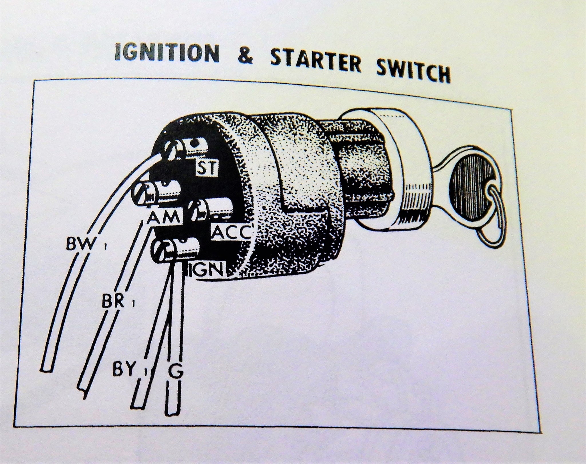
On the old wiring wires are as follows:
Ignition BR
Ignition coil BY
Distributor B
Starter BW

On the replacement wiring I’m working with:
Solid white
B/W
B/Y attached with a solid green.
I bought a ToyotaMatt replacement switch with pigtails. And trying to decipher which wires go to what?
I can’t find a wiring schematic that matches the replacement harness I bought.
I don’t want connect anything backwards and have the replacement harness short out and melt.
Here is a pic of what I am working with:

Any help or suggestion would help.
Cheers
Jorge

CD3B1B9C-FDCD-4936-82F6-86DF49F4A659.jpeg


74481DB7-2B45-4353-A484-9D76E3471A18.jpeg
 
Not sure if this will help
25965bc3-551e-4e60-b415-97b158bdd4a4-jpeg.3245829
 
First off, you must use a multimeter to verify all connections! Secondly, the ignition switch sold to you is for a later model, hence the colour differences.

On the harness you received, this should be as follows (but not guaranteed, check it!) -

Black with white stripe - to starter
White - to ammeter and eventually switched points on the fuse box and the alternator
Green & Black w yellow together - to battery.

My '64' wiring works like this, except for the fact that the white wire in your scenario is black with a red stripe.

The ignition switch should be simple enough to test at which position current flows to which wire with a continuity test
Ok
That makes sense.
Thank you so much for the information.
I will use a multimeter to test and check them.
Cheers
 
my ignition switch pigtail as follows :


- White wire w/ blue tracer stripe ( OLD BLACK WIRE w. / RED Tracer stripe ) = incoming B+ feed from fusible link on battery
(
AM on key switch )


- black wire w/ white tracer stripe = output B+ to starter solenoid to engage starter ( ST on key switch )


- black wire w / yellow tracer stripe = output B+ from key switch to the Ignition circuit of the vehicle ( IG on the key switch )


- blue wire w/ red tracer stripe = B+ output from key switch this is the modern / updated Accessories feature step for a Radio or CB or fog lamps , or tape player , anything u like key in the ACC position ( ACC on the key switch )


- the white wire w/ the blue tracer stripe supersedes the old black w/ red tracer stripe , they mean the same exact thing


- the green wire on this application at the key switch is simply a splice point and should be interpreted that way ,.......
DSCN9847_2048x.JPG

DSCN0672.JPG
DSCN0673.JPG
DSCN0674.JPG
DSCN0675.JPG
DSCN0676.JPG
DSCN0684.JPG
DSCN0687.JPG
DSCN1344.JPG
DSCN1355.JPG
 

Users who are viewing this thread

Back
Top Bottom