Builds 2JZ into 2001 4X4 Tacoma Build (1 Viewer)

This site may earn a commission from merchant affiliate
links, including eBay, Amazon, Skimlinks, and others.

Joined
Jul 23, 2019
Threads
1
Messages
17
Location
Houston
Website
tacupra.com
In brief this is a 2JZ-GTE into a 4x4 Tacoma. WARNING: Image and GIF heavy. This is mostly a copy of my thread in Supraforums, but will try to dig for more content when I find time. Some things will be old, but as a TLDR I have already completed the 2JZ swap with 4x4, AC, and cruise control. My project now consists of compound turbos, 2010 Superduty 1 ton axles, and a marlin crawler dual transfercase tacobox.


The early stages:


I guess I'll start the thread with the brakes:

Brake Upgrade to Tundra Calipers and Rotors

This upgrade is very similar for similar generation 4 runners with the exception of brake lines. The brake lines on the 4Runners are hardline (as opposed to the softlines of the Tacoma), therefore the 4Runners require no brake line fitting modification. Click here for more information.


Details:
Calipers: Stamped "13WL" from an 2006 Tundra 4X4

Raybestos FRC11550

Raybestos FRC11549

Rotors: Factory fit replacement for 2006 Tundra 4X4

Brembo 09.8196.81 UV Coated

Pads: Factory fit replacement for 2006 Tundra 4X4

Brembo P83066N

Factory Tacoma brakes:

Cut Splash guard to fit larger Tundra Caliper:

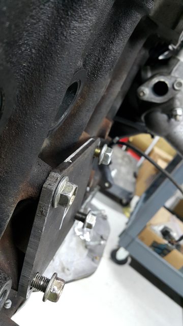
Trim banjo bolts (only two threads is plenty):

Install rotors and calipers:

Install pads and associated hardware:


I will post the suspension soon...
 
Suspension...

Stock setup (with Tundra Brakes):

Pressing out ball joints with OTC press (Part# 7249) and Toyota specific ball joint press adapter (Part# 6733). I was unimpressed by the fact that in combination with the relief cup and the Toyota specific adapter the tool could only get one thread to start. But, it did end up working (Just sketchy):

Upper ball joints pressed out of the spindle.

In order to remove the upper control arm cross bolt you must remove the harness clamp from the inner fender and the airbag sensor. The inner fender does have to be pushed outwards to clear the bolt initially. The bolt does contact the coolant bottle. Applying forward facing torque on the control arm at the last moment will allow you to clear the coolant bottle.
[url]http://i.imgur.com/KX48uLpl.jpg[/url]
The upper control arm cross bolt on the passenger side. You will need to remove the clamp holding the A/C line from the inner fender and the air bag sensor.

Mocking up the Camburg upper control arms.
[url]http://i.imgur.com/S9FdPh8l.jpg[/url]
Close shot of the mock-up.

Cleaning the metal on the spindle for the Total Chaos spindle gusset.

First time welding Mig uphill.
See settings here: [/url]
I was running a generous amount of 75/25 Argon CO2

Prepping for paint.

Fox shocks Factory series with DSC. The key takeaway here is the DSC feature that allows you to adjust High Speed and Low Speed compression valve settings.

I really love the way it turned out. Now all I have to do is get an alignment and tune the valving.

One off Deaver Leaf Springs - Specific to my application.
Increase payload capacity 600 Lbs with minimal lift.

Increased travel!
 
Tracing Tacoma Frame Side Motor Mount

The R154 bellhousing was bolted to the R150F and the transmission crossmember was modified (pushing the full engine/trans assembly back 2-3.4"). The water pump pulley is VERY close to the radiator.


Tacoma Frame Side Motor Mount Flange after cutting trace


Tacoma Frame Side Motor Mount Flange after cutting trace


Trace 2JZ Side Motor Mount


Rough Cut of 2JZ Side Motor Mount Tracing


2JZ Side Motor Mount Flange after cutting trace


2JZ Side Motor Mount Flange after cutting trace


Motor Mount Flanges after cutting trace


Drilling the holes in the 2JZ Side Motor mount Flange


I used a dremel with a carbide bit to cut slots to mimic the factory slots on the Tacoma Frame Side Motor Mount Flanges


Since the engine side flanges were thinner than the factory aluminum flanges the bolts bottomed out in the block before they were able to secure the flange. Trimming the bolts made them fully seat against the flange without bottoming out. After the motor mounts were fully built I used new proper length flange bolts.


This photo shows the trimmed bolt fully seated on the flange.

 
Here is the drivers side engine mount flange.


1.75" Hole saw to match the bushing size.


Start of the notch for the bushings


After taking measurements with the reliefs on the bushings I cut the 1/4" stock to length.


Test fitment of first plates.


Test fitments of second plates.


Cutting of excess material.


Cutting of excess material.


After rough cut of excess material.


Laid down first structural beads with the MIG.


Traced out plates to fully box the motor mounts.


After cutting out the traces for the plates to be used to box the motor mounts


Test fitting of plates.


Test fitting of plates.


Test fitting of plates.


After fully welding the mounts and cutting out more material for weight savings.


Aluminum jigs were used in place of the polyurethane bushings in order to maintain dimensions while welding (polyurethane would have melted).


New proper length bolts to replace trimmed ones.
 
Now time for the transmission mount:


Measuring the original length of the driveshaft to verify my total length after the cut. This point is the mounting flange at the front of the carrier bearing.

The R154 bellhousing was bolted to the R150F and the transmission crossmember was modified (pushing the full engine/trans assembly back 2-3.4"). The engine is as far forward that it can go since the water pump pulley is VERY close to the radiator.


This is the measuring point at the back of the output flange. The front half of the shaft is cut 2-3/4".

Measurement taken from the flange to front of carrier bearing bracket: 27-3/4"

After modifying transmission mount: 25"


Rough cut of 1/4" extension flange and gussets.


Mig settings for this weld job


Gas settings for this MIG job


First tacks


First beads


I used a straight edge to replicate the location of the transmission mount holes.


A hole saw made a perfect sized hole for the transmission locating bushing.


Weld was a little close to the mount holes. Though the washers and bolt heads clear it (Just).


Cleaned off the top weld since the transmission mount has a flat metal flange. I didn't want the weld to disturb it from sitting flat on the face.


Traced the rear of the hole in the transmission tunnel.


Used a straight edge to mark my cut back. The traced cardboard replicated the back of the cut. (2-3/4" back)


Telling myself to not mess this up.


Came out pretty well. Everything clears.


Transmission mount fits/clears everything it needs to.

The R154 bellhousing was bolted to the R150F and the transmission crossmember was modified (pushing the full engine/trans assembly back 2-3.4"). The water pump pulley is VERY close to the radiator.

The factory bolts are M8 x 1.25 x 14mm, you will need M8 x 1.25 x 22mm for the 1/4" plate.


New shortened driveshaft balanced with new carrier bearing and new U joints. Only the front half of the shaft was shortened 2-3/4"

Front section of driveshaft had to be re-tubed as the factory shaft is tapered. I was advised that shortening a tapered tube was difficult.

 
Here is some stuff you folks should like. Not in chronological order, but a good idea of how it looked when the initial 2JZ conversion was completed.


7cRB4SKh.jpg

Full res photo here


DyTwqBRh.mp4
 
Last edited:
Can't seem to post media content now. As the toolbar on top is grayed out. Will try later.
 
Last edited:
Still can't seem to embed media or photos natively as the toolbar is grayed out.

Here is an imgur album for some of the cooling system(Click image below):
 
Last edited:
Looking real nice! I like it.
Thanks bud!

Also here is an imgur album with some of the intake plumbing including water to air intercooler plumbing:
 
Last edited:
Here is an imgur album with the oil cooler setup and electric pusher fans(It does keep the 2JZ Cool even in Hot Summer Days in Houston Traffic after pulling a loaded car hauler w/ AC on full blast):
 
Impressive and informative. What made you come up with this type of setup? Just wanted to build something better than an s-runner?
 
Impressive and informative. What made you come up with this type of setup? Just wanted to build something better than an s-runner?

I just wanted a platform that I can continue to build up if I got bored. Which I am glad I picked the 2JZ because it is an excellent Truck engine and responds so well to upgrades. The EFR 7064 I have on there now with a quick spool valve and super short intercooler plumbing (and water to air for less pressure drop) makes it very responsive. It started building boost at 2k and would reach 20psi at 3k rpm. The problem was the top end. It only managed 10 psi at the 6800rpm redline. Compound turbos will solve the gap at the top end while still benefiting from the super responsive low end. Numbers on the dyno with the single EFR 7064 were 316whp and 405 ft/lbs of torque.
 
Reading your build got me thinking about this 2JZ GTE

I think it is great you did this and opensourced your knowledge. Hard to tell how many parts get saved from scrap to become someones hobby.
 
Reading your build got me thinking about this 2JZ GTE

I think it is great you did this and opensourced your knowledge. Hard to tell how many parts get saved from scrap to become someones hobby.

Thanks man. The build has it's challenges and documenting adds more work, but if it helps anyone it is worthwhile!


Imgur Album for Brake booster modification to fit 2JZ Intake Manifold. Click Image to go to Album:

 
Imgur Album for power steering and AC Lines. Click image to go to album:
 
Imgur Album for testing fitment with cast manifold and quickspool valve with single EFR 7064. Click image to go to album:
 
The second EFR has arrived. EFR 9174 for the primary in the compound 2JZ setup. (Left: EFR 9174 Primary Right: EFR 7064 Secondary)

1DOGZtUm.jpg


A2Sq0gbm.jpg
 

Users who are viewing this thread

Back
Top Bottom