22RE Alternator Wiring (1 Viewer)

This site may earn a commission from merchant affiliate
links, including eBay, Amazon, Skimlinks, and others.

Joined
Sep 11, 2012
Threads
56
Messages
690
Location
Rossland, B.C.
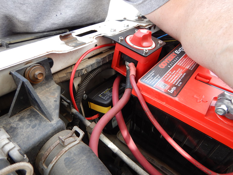
Truck is a 1990 22RE. Canadian version, although that doesn't change too many things. I've done a bunch of searches on here and other sites, and I'm working from my FSM. I'm not excellent with electrical, but slow and careful. I can use some other eyes to confirm what I'm seeing in the FSM. First, I'm trying to return my alternator wiring to stock. Second, I want to duplicate the alternator circuits to run a second alternator to charge a house battery. Longer term goal during a pandemic. Alternator that is currently in there is likely a Tacoma alternator from a 1995/6 or so. Different plug but similar alternator output. Works, but seems to put out more than 14.4 volts, or voltmeter is off, maybe. Original plug should look like this:
20200516_155848.jpg

1. Red wire is 16 gauge? Goes to 10amp fuse in driver's side kick panel. Ties into Ign and turns alternator on, correct? This is part of circuit marked "F" in FSM. When ignition is on, it connects to "B" circuit, upstream of 80Amp Alt fuse (underwood fuse box), which is upstream of fusible link to battery positive post.

2. White wire is sensor wire. 14/12 gauge? Goes from alt plug above to "D" circuit. D circuit goes to large fuse in underwood box marked AM1, 40 amps. Then it connects or splices into B circuit upstream of 80amp alt fuse. I can't see exactly how it is spliced, because I think it is under the box.

3. Yellow wire from plug. 14/12 gauge? goes to 7.5 amp fuse underwood marked Charge. Correct? Then it goes to charge warning light and to IGN fuse 7.5 amp in DS kick panel? Also connected to 10amp fuse for gauges? Like voltmeter. Then ties into "G" circuit, goes to IG 2, then to AM2 Fuse (30 amps), then connects or splices before fusible link? This part is the most confusing. Can alternator run without this? Only sacrifices warning systems? or alt won't run without this?

4. Big wire from Alt marked Batt. Not shown. Looks about 10 gauge. Runs up under air intake box. Spliced through small black box on DS fender where one branch runs accessories? Main wire runs along front clip over radiator to fuse box, through 80amp alt fuse, to fusible link, to Batt + post.

Small black dots are splices or connectors in FSM? or both? Best way of connecting wire to wire?

Any major errors that will cause shorts or fires? I will eventually post in power systems as well, since that's where this is headed.
 
Thanks GNOB. I printed that off of Bike Man Brent's thread. Easier to read than my 6 page pullouts in the FSM. My 1990 has different AM1 and AM2 fuses. Not sure if it matters. I still can't tell if I actually need the yellow wire - charge warning circuit to make the alternator work. I also couldn't find out info on what Toyota uses for splices, without digging into the harness to see. Maybe solder and heat shrink all splices? I want to avoid the little clamp style plastic things that were used by whoever installed the stereo.
 
I'll revive my own thread. Still working on this project. Advancing slowly. In theory, it will work. I am busy running wire through the firewall to various places. The charge warning circuit is still a headache. Seems like it would be nice to know if my second alternator or battery weren't charging. Does anybody know the physical location in the mini trucks or 4runners of the diode in the charge warning circuit? In the diagram posted above, it looks like it could be right next to the light, in the gauge cluster, but maybe it's elsewhere? Anybody have an idea of size, type, model of the diode?
 
Interesting that there is a diode there at all. Domestic stuff doesn't bother with one.

Why not a Voltage Sensing Relay or Automatic Charge Relay (w/ or w/o a battery bank switch) instead of a whole second charging system? Not critical, just curious about your logic path.
 
If I'd known how much work it was going to be, I might have chosen a different logic path. Here's the original path: try to preserve the starting battery totally for starts after sitting in remote places in -25 or below. Need every amp in the start battery for this. I read enough on the various switches, dual battery setups, charge relay problems, systems requiring compatible batteries, and so on, that it looked worthwhile to try setting up a completely separate charging system and house battery, with solar added in eventually. I have a spare pulley because I have no A.C and I have several alternators kicking around. Seems simple enough, but it's been pretty tedious to get it all in place. We'll see if it works and is worth it. The diode is indicated in most diagrams of mid 80's to late 90's or later Toyotas, and is definitely in the FSM. Not sure where it is physically. I worked on installing a fuse block tonight, so did not pull the cluster to look for a diode. Not sure if the diode is necessary either, but I assume Toyota put one in there for a reason. I will probably try the system without the charge warning for the time being, and finish it later when I know more about what I'm doing. If the fridge and lights kill the house battery, I will know about that pretty quick. I think the fridge has a charge monitoring cutout switch, which will be a bit like a charge warning light.
 
If Mr. T put a diode in that circuit I'm quite sure that it is necessary. I was more commenting on the differences than suggesting that you don't need it.

From my forays into this topic what I've deduced is that when there is something charging them both the batteries don't need to be identical. It is when they are just sitting or being discharged while connected that they need to be, ideally not just cousins, but brothers. Maternal twins would be the best. The root of the problem is that even if they are sequential serial numbers they will have slightly different internal resistances. That sets up a see-saw self-discharge cycle that ultimately kills one of them. BT, DT.

With an ACR/VSR that only connects them under charge, and disconnects them when the charge is removed the need for them to be twins goes away. That said, I made a point of connecting the house battery ground to the same bolt that the starting battery ground is connected to on my most recent dual battery install, and I was seriously thinking of taking the house battery ground all of the way up to the starting battery's ground terminal. I didn't because I was running out of room up there. The + terminals are both, first, connected to a marine battery bank switch. And then whatever else is connected to them uniquely has that connection made at the switch's terminals. The Blue Sea ACR connects to both switch terminals and it's ref ground is on the same bolt as the starting battery's body ground wire.

By wiring the battery bank switch with large cables I can pair the batteries for a hard start or winching (if I ever put a winch on that truck). Can also use the house battery as the starting battery alone should the starting battery die in the field.

Pic of the install with some tidying still needing to be done:
i-8RT2T3j-L.jpg
 
Yes, I read a lot about the batteries needing to be "brothers". If I had to do it again, like in 5 years or so, I would probably not try the separate system. I do occasional winter starts where no block heater can be plugged in, so I don't want any accidental draw down on the start battery. In theory, I can jump the start battery from the aux. batt in cold weather, no matter what system I end up with. What do you have running off your aux battery? I have a winch installed but not wired yet.
 
Right now the aux in that truck only has a 2M radio running off of it. Sitting with the radio on for 13 hrs during the Parker 425 and running all of that remote pit's comms with that radio got me to thinking that it ought to be on a separate battery. In the near future the iPad based GPS and all of the power-points in the cab will be wired to it. One of those power points is for a fridge. I'm debating adding a small inverter that will be hard wired and be connected to a normal outlet in the side of the console extension that I'm about to build to support the GPS.
 
I pulled my cluster off yesterday, just in case the diodes were easily accessible. They are not. There are 5 diodes in the cluster, with little diode symbols in various places on the blue flexi circuit board. I will try the system without the diode or charge warning light until I can figure out the diode type.
 
If you don't want to work that hard, the diode sold by MSD for use with their IGN systems on a vehicle with a GM alternator will probably work well. W/O that diode GM's have a feed-back problem that causes the engine to run after the key is turned off and the diode fixes that. It is installed in the excite wire of the GM alternator.....

EDIT:
I used one of these for this purpose on a customer's flat fender complete re-wire project: ACDelco Replacement Diodes 88987713 The wiring kit supplied used mini fuses, so it was easy to add that to the circuit for the excite wire. I'm a fan of using these for the ATO fuses: Waterproof In-Line ATO/ATC Fuse holder - Blue Sea Systems, but I've not yet found one that works for the smaller mini fuse size of the linked above diode. Could use it with the diode linked below with some spade terminals if you wanted it easily replaced.

FWIW these are what MSD supplies: Diodes Based purely on their apparent size I'll guess the 3 amp version.
 
Last edited:

Users who are viewing this thread

Back
Top Bottom