1985 BJ70 Wilson Switch Installation (1 Viewer)

This site may earn a commission from merchant affiliate
links, including eBay, Amazon, Skimlinks, and others.

Joined
Aug 29, 2002
Threads
145
Messages
2,018
Location
Port of Indecision...otherwise Northern Arizona
I'm starting this thread to have a BJ70 specific thread for the infamous "wilson switch" mod., when, inevitably, the OEM glow plug timer goes tits up. I'll add to my first post as I complete the mod, but will also ask for assistance from those mudders who are more experienced than me, since this is my first oil burner.

The Rig: 1985 BJ70, 12V, w/superglow, 3B motor.

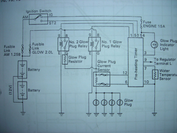
Here is the OEM wiring diagram for the glow plug circuit:

476842765_JyGF6-M.jpg


Here's the corresponding plug locations:

476842767_PcvEC-M.jpg


Here's what the timer looks like behind the glove box (Left hand drive):

476846280_SsYzP-M.jpg


...and here's the inside of one of these timers:

476867926_2zmvt-M.jpg


What I'd like to do is have the wilson switch activate the Glow Plug Indicator Light and glow plugs, but I'm a bit confused, not being an electrical guru, in where to wire the switch to bypass the timer.

I've read the other posts, as well as Greg_b's write up, but am a bit lost when it comes to the superglow system on the 70.

So...where goes the switch?

-H-
 
Last edited:
After reading pages and pages of "Wilson switch" search results and Greg_b's post, which is the main basis for the whole shebang (and the progenitor of the name, natch) I thought I would post up my process for a Canadian 85 LHD BJ70- not to hijack this thread but since it's 2 years old...

Okay, so the first thing is since you want to do a decent job and put that fancy pushbutton switch in a good location, the first specifically BJ70 advice is- that it takes longer than a half hour if you don't know exactly what you're doing. I sure didn't.

Your timer switch is up above the glovebox compartment (as above photos) and if you want access to the glovebox, the central panel (where I mounted the switch, below the heater controls) and the glow lamp, you have to pop all three of those sections off. If you regularly go back here, great, it's probably all tidy and zip-tied. For the rest of us humans, it's dusty and you discover lots of lost treasures. (Who knew I had a key buzzer?)

Since I was working through the Greg_b post as I went, I had to discover this piecemeal and wasted a lot of time hunting around the kick panel for nothing.

Using the above photos of the wiring harness to the timer helped me ID the bypass candidates: one black and red on the left in the photo and one black and orange on the right. They correspond to #5 and #1 on the FSM diagram, but I didn't know that at the time, so I did as the post said and popped some wire in the harness and ran it to the +POS on the battery while the trusty voltmeter waited.

The first attempt was clearly #5. The squareish relay mounted in the body panel left of the driver-side battery was the one that went off, and the voltmeter read 2.8 V at one of the plugs.
Second try, #1 (black and orange). The little cylindrical relay went off, and the plug read ~8 V.
This is all with the key in the “ON” position, of course.
If it's your first time looking at the timing unit wiring harness, notice that the pattern is asymmetric with #6 position off by itself- that should help orient you.

Now, with the proper main bypass identified, you go about the quotidian business of cutting the glow lamp light's wires (key's off now, btw!). The black and yellow wire is powered when the key is in “ON” position, so wire the live end to one side of your switch.

The other side of the switch has two wires- one to the previously identified #1 wire at the timing unit (that you clipped between harnesses or somewhere you can work with it) and the other to the remaining stub of black/yellow wire at the glow lamp.

Run the red/white wire from the lamp to an appropriate ground (steering column in my case) and you should be ready to test the system. You should now have the high glow relay at your fingertips when the key is on. The rest I'll leave to the experts here on MUD who have detailed all of the remaining things to consider; glow plug voltage, how long to glow, etc.

I plugged the timing unit back in after all this but have no idea if secondary glow even works, or has worked... did it turn the glow lamp on in a stock BJ70 when secondary glowing? I never saw it.

Thanks to the original posters of all this info and to the crowd for answering questions- I love mud. I mean, I h8 it.

e
 
Please throw them up. Im glad to see that I am not the only one who doesnt understand the directions that are up here. They dont quite mesh with the factory wiring diagram (that and the factory diagrams have no legend telling me what each letter means in terms of color). So far, 1134 is the only one who has thrown up directions that I can understand.

One wire goes to the main glow relay (the round one) and the other goes to the after glow relay (the square one). You take the wire that goes to the round, main glow relay and pull it out of the harness. You leave the after glow relay wire intact (correct?). Next, you take the switched power wire off the glow lamp and wire that to one side of the switch (lets say the right side). Now, there is the other side of the switch (the left side). What goes there? The wire that triggers the main glow relay (round one)? Then, what happens to the other end of the glow lamp? I ground that one?

A typical momentary switch, like pictured, only has two spades. So one is the keyed power switch from the glow lamp and the other is the power wire that used to go from the glow timer to the main glow relay. Keyed power in and relay power out. What about the wire that used to be on the other end of the glow indicator lamp? Do I just ground that directly?


Oh, and where is the resistor that needs to be removed located?


edit: What about the use of a 4 pole momentary switch? One set of poles going to the glow system and then the other set going up to the now unused glow lamp? Am I right in thinking that if something like this is used, when you hit the button, the glows will activate and the lamp will light?
pRS1C-2160417w345.jpg
 
Last edited:
One wire goes to the main glow relay (the round one) and the other goes to the after glow relay (the square one). You take the wire that goes to the round, main glow relay and pull it out of the harness. You leave the after glow relay wire intact (correct?). Next, you take the switched power wire off the glow lamp and wire that to one side of the switch (lets say the right side). Now, there is the other side of the switch (the left side). What goes there? The wire that triggers the main glow relay (round one)? Then, what happens to the other end of the glow lamp? I ground that one?

Thanks derelict- As soon as I ID'd the primary and secondary relays, I just worried about the primary. Clip it from the harness and yes, connect it as you've said, to the left side of your switch.

Maybe it's easier to think of it as: one switched power in (->) MOMENTARY SWITCH (->a) wire to primary relay (->b) glow lamp black wire. Both (->a)(->b) are on the same pole of the switch.

Then ground the white/red wire off the glow lamp, as you've said. Your switch is doing two things when you press it: turning on the lamp and flipping the relay.

A typical momentary switch, like pictured, only has two spades. So one is the keyed power switch from the glow lamp and the other is the power wire that used to go from the glow timer to the main glow relay. Keyed power in and relay power out. What about the wire that used to be on the other end of the glow indicator lamp? Do I just ground that directly?

Oh, and where is the resistor that needs to be removed located?

edit: What about the use of a 4 pole momentary switch? One set of poles going to the glow system and then the other set going up to the now unused glow lamp? Am I right in thinking that if something like this is used, when you hit the button, the glows will activate and the lamp will light?

I just ignored the resistor, but on the above wiring diagram it looks like it's after the secondary relay. I can think of where in general it would be under the hood but I haven't ever positively ID'd it.
 
Thanks derelict- As soon as I ID'd the primary and secondary relays, I just worried about the primary. Clip it from the harness and yes, connect it as you've said, to the left side of your switch.

Maybe it's easier to think of it as: one switched power in (->) MOMENTARY SWITCH (->a) wire to primary relay (->b) glow lamp black wire. Both (->a)(->b) are on the same pole of the switch.

Then ground the white/red wire off the glow lamp, as you've said. Your switch is doing two things when you press it: turning on the lamp and flipping the relay.

Great, thanks for this. Ill see if I can get something set up this week some time. I just rebuilt my injectors last night and holy **** what a difference they make.

Im a visual learner when it comes to electrics so does this look right? Im going to get a lit switch that glows when its active and use that as the indicator lamp. I have an idea for the opening where the original glow indicator lives.
Glow Diagram.jpg
 
With the intention to add some content to this thread, I will add some information and my experience when installing the Wilson Switch.

Following the text posted by "eleventhirtyfour" and using the images of the Factory Service Manual posted by "Hltoppr" I went out and started working on my 1985 BJ70 to install the switch.

First, I bought a temporary switch from Drew (amaurer) at Knoobs.com, Custom Switches and Knobs. If you haven't talked to Drew yet, he is a great guy and great person to deal with. I wanted to keep a factory appearance so I asked Drew to replicate the knob of the factory hand throtle. Drew did an amazing job an used the factory glow symbol on the knob.

Here is a photo of the knob:
IMG01709-20120123-1705.jpg
 
Looks like you got the wiring straitened out. Its always a good option to have a backup in the event the glow timming fails. Now, I need to do this as well as make a cable for my edic in the event it fails some day.
 

Users who are viewing this thread

Back
Top Bottom