hi-po 1FZ - cylinder head (1 Viewer)

This site may earn a commission from merchant affiliate
links, including eBay, Amazon, Skimlinks, and others.

bjowett

Supporting Vendor
Joined
Oct 28, 2002
Threads
295
Messages
4,367
Location
North Adams, Massachusetts
Can't ad this to the winter hi-po project thread... for some reason ?... so a new thread

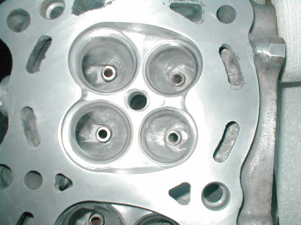
Pulled the head and disassembled it today.... boy does it need some flow work. Let the porting begin! For those wondering, the diesel will probably go in another cruiser.

P1010256_0.JPG
 
Last edited:
Brian,

How did the HG look?

-B-
 
So Brian what are you taking about? From what I've read and what I saw when my head was off, It looked like Toyota did a fairly good job. Everything I read was about matching the gaskets to the ports for turbulance and having a clean port as well. The one big warning was not to just hog out a bunch of matterial thinking this would be better for flow when in turn it would adversely affect the fuel velocity and screw the pooch on the low end.
 
So does porting the head affect the horsepower-torque curves by lossing low end torque? I thought that was accomplished via cams?
 
My understanding is that you want the runners to the head (intake) and out of the head (exhaust) to be matched and in such a way as to allow easy passage. After some searching on the web it mostley talked about domestic production engines. The first area they focussed on was getting the head and manifolds to match to the gasket. Any time you have an uneven seam you create turbulance which reduces the flow. Another area was casting anomolies where a rough edge or bump would also create turbulance.

The big warning was that if you enlarged the opening to the head enough, while you would see an improvement in the higher rpms because of the greater flow, you would see a decrease in the lower rpms due to the fact that the decreased flow rate would allow the gas to de-atomize from the air and actually have an adverse affect on output.
 
B, the HG looked good on this motor, 110k I think.

Rick, the ports on this head, IMO, are tuned for emmisions. The transition from the longside turn (top of the port) into the throat of the port is horrible. Toyota did a decent job matching the throat to the valve seat, but the machining done to accomplish that leaves a huge bump there (long side).

A nice mild port job should not lose any low end.... This is a big six, there is plenty of power hiding in it.
 
I lost no bottom end when I ported and polished my head, the bottom end was way better, as I had more low end grunt to climb stuff when needed, and I could ilde the trail in second gear most of the time as to revering high in first. Just my observations. Good luck brian. later robbie
 
robbie said:
I lost no bottom end when I ported and polished my head, the bottom end was way better, as I had more low end grunt to climb stuff when needed, and I could ilde the trail in second gear most of the time as to revering high in first. Just my observations. Good luck brian. later robbie

Robbie,

Did you reuse the stock cams or did you use a regrind?

What else did you do to that bad boy?
 
Here's a picture of the port, the magnetic pick up tool is point at the rather large bump remaining after machining.

P1010266_0.JPG


Hey Robbie, what did you do (if you don't mind sharing?) around the valve guide? There is a wierd recess there, pretty much packed up with carbon in this head. Also the trailing patterns of built up carbon and heavier deposits on one side of the valve make it look like there is some real power hiding in there.
 
Last edited:
Where you are pointing i smoothed almost to the seat. I also clean up the neck area and smoothed out the radius (I hope you can see this). Too the area around where the gaskets I opened up too the gasket on both the head and manifolds(yes I cleaned and polished both the intake and begining of the exhaust)It did take me all of 10-11 hrs of work. The bends after the begining of the air chamber had too much of a bend for me and I made the bend not so sharp. I polished everything up very nice. I also tried to make them as even as possiable from cylinder to cylinder. There was quite a bit of Aluminum on the bench and floor when i was done. Hope you use some sort of air mask, I did. It would not be that great with out one.
No I did not have the cams reground. I am not a big fan of reground cams. If too much grinding, you could not have enough shim thickeness to make them be in specs. I personally would use a new cam if they could be had. Hope this helps later robbie
 
Looks good Brian! :bounce:

How much do the valve guides stick out into the port? On heads where there is a bunch of guide exposed, we would taper the exposed part of the guide in the lathe before installing. On heads with little exposed, we would install the guides and port them smooth with the surface, then run the reamer through the guides to clean up the burrs. Made a big difference on the flow bench and if your not removing much guide it won't affect longevity.
 
ooooo! just beautiful!
 
The intake guide has a wierd recessed pocket around it... so it hardly protrudes into the port. I've never seen anything like that in a cylinder head, so I pretty much left it alone. Any idea's on that?

The exhaust guide and surrounding port are fairly standard looking, it sticks out into the airflow a teeny bit, so it will get turned down.
 
To bad you couldn't bench flow the head before and after. Even a crude bench could work. A wooden box with a shop vac, a large bypass valve and absolute pressure guages would be great. I might be able to score you a flow meter to use for the test. Testing and matching air velocity and the absolute pressure differental on each cylinder would be cool. Here is a link on a crude flow bench.
 
There are some similar plans in one of the porting books I have... thought about it... will probably build one someday. For now I will rely on port measurements to keep things matched. It would be nice to know though... dang you Cattledog! I have enough on my plate as it is. :D
 
Thanks for sharing the pics. Pics of this work are critical. Porting and polishing the head while replacing the HG is easier to swallow than just PM the HG. I am sure you will find more power in the head. What and how are you going to measure the ports? :beer:
 
A set of inside spring type calipers works well for taking measurements in the ports... various cross sections at certain depths into the port are measured, they can then be easily duplicated in all ports.
 
bjowett said:
The intake guide has a wierd recessed pocket around it... so it hardly protrudes into the port. I've never seen anything like that in a cylinder head, so I pretty much left it alone. Any idea's on that?

The exhaust guide and surrounding port are fairly standard looking, it sticks out into the airflow a teeny bit, so it will get turned down.

That type of contour around the intake guide is newer, my flowbench days are old school, to remove it would require major port reshaping. I would leave it other than smoothing it when the guide is out, when the new guides are in I would grind them at an angle even with the lip if the port and round the side of the guide facing the airflow. If the exhaust only sticks out a little bit, I would install the new ones and grind them flush. Pictures of the ports from the other side would help.

We experimented with junk heads and the flow bench for new port shapes, it's easy to make something that looks good, but doesn't flow so well. So without that data I like to be conservative and just cleanup the bumps, match and smooth. The other thing we did with junk heads was cut them up on the bandsaw to see how much meat there is, it sucks to cut into a water jacket! :whoops:

Most of the time for street use, a fine sandblasted surface is best for the intake port and full polish for the combustion chamber and exhaust. To polish the valves we chucked them in a drillpress at full speed and shined them up with emery cloth.
 

Users who are viewing this thread

Back
Top Bottom