Thank you for all the advice and 3D rendering, this is EXACTLY why I am a member here, and do what I can to help others! Thank you guys for being my sounding board, it is always nice to have someone to bounce ideas off of.
Square tube would be best. Easier to work with at corners than I beams or channel, and much better torsional strength than them as well.
This is what I was thinking as well, at least in the aspect of ease of fabrication. Torsional rigidity duly noted, and I will stick with that.
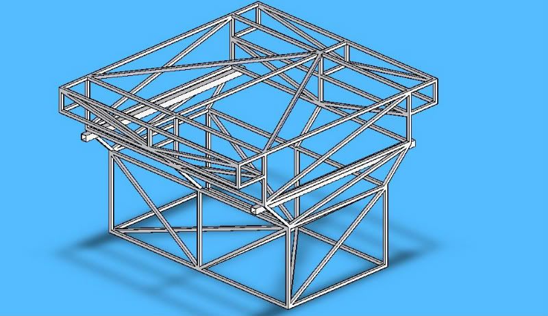
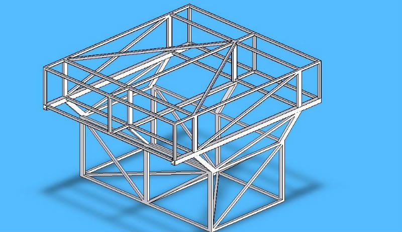
All of the diagonals make it a bit confusing, but this is modeled as sharp cornered (putting all of the corners is WAY time consuming) 1" square tube x 0.065" wall with the jack tubes being 2" x 0.125" wall. SolidWorks predicts it to weigh ~220 lbs.

While it is not precisely what I was looking for...

[/sarcasm] it is a great way to see the skeleton without me needing to break out the colored pencils and a gin and tonic again!
Looking at ntsqd's diagram, which I think is overkill from what you are talking about. Gives me the idea that what you are talking about will work. But if the slide out is to be full of equipment, a tent, cooking stuff, sleeping bags and all you are looking at most likely 400 pounds on your jacks.
Depending on the surface size of the jacks, the plate that welds to the trailer, I would go just a little bigger. I was thinking the surface is about 2.5 inches square, therefore the the 2x3 box 120 wall would work perfectly. You want something to weld to that is flat in this situation I think. I would run the 2x3 the lenght of the box at least, but most likely would make it at the top of the trailers, and use it as the base for the rest of it. It will not add that much weight. 2x3 box is very strong.
Your main concern will not be it lifting, but it being ran into by something when off the trailer, the 2x3 would give you a more solid base I think.
You have a great idea, and it makes the trailer way more useful.
The jacks are going to mount to the arms of a T made of either square or rectangle tubing, and the leg being the bit that slides into the lifting frame members. Because the jack assemblies will need to be removed, turned 90deg, and slid back in for storage, I can't use rectangle tubing... unless I am not reading your thoughts well enough.
Last night I was kicking ideas around in my head... hope this makes sense.
Starting with the empty trailer, form a U of channel iron that is slipped over the bed rails of the trailer, with a angle iron closing the square at the tail gate opening. This square will provide positioning and with a weather seal inside, keep the elements out of the trailer when the module is mounted. On top of that, two lateral 2" square tubes, of the female receiver hitch dimensions, the lifting tubes, will be welded. Another two frame members will connect those tubes, longitudinally about the trailer, again completing the square and the base frame of the module.
From there I will need two secondary structures, the "hanging" structure below the frame, and the "lifting" above.
The hanging structure will fit within the confines of the trailers bed, following the contour closely. When the module is off the trailer, this area will need to support the hanging weight of two wooden drawers on sliders. While the contents and configuration of the drawers/storage compartments may alter, I am assuming I will have between 400 and 500lbs of weight being suspended by the hanging structure while on site.
The lifting structure will need to support the weight of the RTT, two adults, camping gear, and other stuff normally placed inside a RTT. this will obviously reside on the outside of the structure, while the inside will be used for equipment/food/water storage. I would like to keep the heaviest items in the hanging assembly, but I am assuming another 200lbs of storage plus the 400lbs of adult and gear inside the tent when in use.
So, I guess my only real concern is the type of material, and number of supports, that will be needed to construct the two substructures. The top structure, I am going to assume, can be made of the 1" square tube, as it only has to disperse the weight onto the main lifting frame and hold a skin on. The problem comes from the hanging structure... or am I over thinking it? Now looking at things, .065 will be WAY too thin for the project. What material would you all suggest?
Keep the ideas and questions coming!