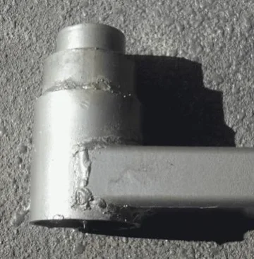
Here is what I built, with instructions following.
(As the site limits attachments to 3 per post the 6 pictures will have to be spread over 3 posts)

There are 2 parts to making one of these – a stub axel and a hub to hold the axel bearings.
These instructions apply to Australian sourced parts. I’m sure parts in other countries will be similar, though maybe not exactly the same, . . . so maybe someone who knows can supply the exact Bearing Part numbers and pipe sizes to suit for common American our European, etc trailer hubs and stub axels.
The Stub
In Australia the most common trailer hubs fit stub axels that were used on Ford and GM designs from the 1970s. The inner diameter of the bearings are different by 1/8” (Ford is bigger) but the trailer hubs (due to careful selection of roller size) can use the same outer diameter bearing races so that the ‘standard’ trailer hubs fit both types of stub axel. The hub described here will fit either the GM or Ford stub axels too (when the appropriate bearings are used).
GM is also known as LM stubs using LM11910/11949 outer bearing, LM67010/67048 inner bearing and LM28560 seal
Ford is also known as SL stubs using LM12710/12749 outer bearing, LM68110/68149 inner bearing and LM28600 seal
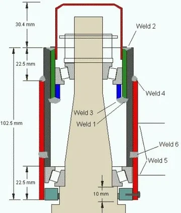
The finished hub will be about 70mm in diameter by 102.5mm high and you will need at least 10mm clearance height below the oil seal support and 40mm clearance above to fit the nut and dust cover (so total clearances are about 75 x 155mm (3” x 6-1/4”).
Select a bearing type (either Ford or GM will be more than adequate), buy a stub axel from Super Cheap, etc, and buy a set of matching trailer bearings (including top cover) at the same time. Weld the stub into an appropriate position in a solid rear bumper (taking the clearances and swing path into consideration).
The Hub
DO NOT cut the flanges off of a cast iron wheel hub and then attempt to weld to it – welding is almost impossible with cast iron, and certainly unattainable for an amateur.
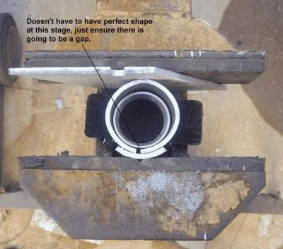
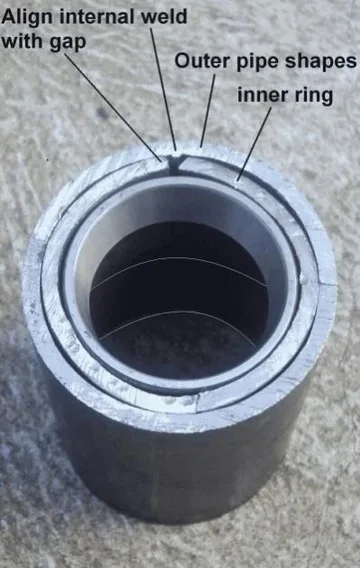
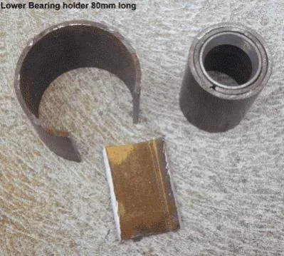
A hub can be made quite easily from a few short pieces of steel pipe. Unfortunately only the middle section will fit ‘as is’ while the other three pieces will have to be fabricated, pressed into a curve and welded into place. This is not as hard to do as it may sound, 30 minutes or so with a hacksaw, file, hammer, a strong vice, arc welder and a bit of patience will create the four pieces. A drill may be required for optional plug welding and grease seal pining.
Sizes Table

Next part is fabrication


(As the site limits attachments to 3 per post the 6 pictures will have to be spread over 3 posts)
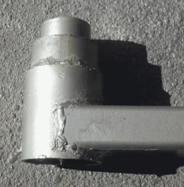
There are 2 parts to making one of these – a stub axel and a hub to hold the axel bearings.
These instructions apply to Australian sourced parts. I’m sure parts in other countries will be similar, though maybe not exactly the same, . . . so maybe someone who knows can supply the exact Bearing Part numbers and pipe sizes to suit for common American our European, etc trailer hubs and stub axels.
The Stub
In Australia the most common trailer hubs fit stub axels that were used on Ford and GM designs from the 1970s. The inner diameter of the bearings are different by 1/8” (Ford is bigger) but the trailer hubs (due to careful selection of roller size) can use the same outer diameter bearing races so that the ‘standard’ trailer hubs fit both types of stub axel. The hub described here will fit either the GM or Ford stub axels too (when the appropriate bearings are used).
GM is also known as LM stubs using LM11910/11949 outer bearing, LM67010/67048 inner bearing and LM28560 seal
Ford is also known as SL stubs using LM12710/12749 outer bearing, LM68110/68149 inner bearing and LM28600 seal
The finished hub will be about 70mm in diameter by 102.5mm high and you will need at least 10mm clearance height below the oil seal support and 40mm clearance above to fit the nut and dust cover (so total clearances are about 75 x 155mm (3” x 6-1/4”).
Select a bearing type (either Ford or GM will be more than adequate), buy a stub axel from Super Cheap, etc, and buy a set of matching trailer bearings (including top cover) at the same time. Weld the stub into an appropriate position in a solid rear bumper (taking the clearances and swing path into consideration).
The Hub
DO NOT cut the flanges off of a cast iron wheel hub and then attempt to weld to it – welding is almost impossible with cast iron, and certainly unattainable for an amateur.
A hub can be made quite easily from a few short pieces of steel pipe. Unfortunately only the middle section will fit ‘as is’ while the other three pieces will have to be fabricated, pressed into a curve and welded into place. This is not as hard to do as it may sound, 30 minutes or so with a hacksaw, file, hammer, a strong vice, arc welder and a bit of patience will create the four pieces. A drill may be required for optional plug welding and grease seal pining.
Sizes Table

Next part is fabrication
Last edited:


