HJ60 headlight diagram request (1 Viewer)

This site may earn a commission from merchant affiliate
links, including eBay, Amazon, Skimlinks, and others.

So the schematic does exist for these rigs. Thanks for posting that. Any chance of seeing a little more of the schematic? Like up and to the left? What you have posted is very helpful.

Thanks.
 
So the schematic does exist for these rigs. Thanks for posting that. Any chance of seeing a little more of the schematic? Like up and to the left? What you have posted is very helpful.

Thanks.

I'll give it a try, but the forum down sizes the pic.
Send me a PM with your email address and I'll get you a copy

1981 BJ40 series USA & Canada 24V.jpg

Rudi

1981 BJ40 series USA & Canada 24V.jpg
 
They exist for the BJ40 24V, not for the canadian HJ60
 
Hello again Rudi...I am using a small trickle charger every couple of days in an effort to keep the two batteries fully charged to the same level.
Given my situation, what would you do?

What would I do? Study the diagram until you fully understands how it works.
Get the voltmeter and start checking it out.
Does the relay work?
Do you get the right voltage at the right wire color?
And so on.

Remember: Left head light is 0 and 12V, Right headlight is 12 and 24V (thus 12V).
The trick is in the little wire with the fusible link that is hooked up to the negative stud of the High side battery. That wire proves the 12V for the right side headlight AND the voltage for the relay.

Rudi
 
They exist for the BJ40 24V, not for the canadian HJ60

You're right. I've never found a complete Canadian HJ60 diagram, but...............

The BJ and the HJ use the same relay and given the internal wiring of that relay there is no other way to hook it up.
So, here is your homework..... (I'm too lazy for this)
Cut and paste the BJ diagram into your HJ diagram and....... Voilá!
Even the wire colors are the same.

Rudi

I've also an explanation why there is no complete wiring diagram.
When a change is made for a small series of production the factory sends out an "addendum" which should be added to the workshop manual.
 
Last edited:
What would I do? Study the diagram until you fully understands how it works.
Get the voltmeter and start checking it out.
Does the relay work?
Do you get the right voltage at the right wire color?
And so on.

Remember: Left head light is 0 and 12V, Right headlight is 12 and 24V (thus 12V).
The trick is in the little wire with the fusible link that is hooked up to the negative stud of the High side battery. That wire proves the 12V for the right side headlight AND the voltage for the relay.

Rudi

Or one could just rewire the headlights for 24v as I've done, and am still using very successfully ;) Thanks again Rudi! If I'm ever down your way, I'm buying you a beer!
 
I was assuming that there was a broken wire, or a "parasitic draw"somewhere.
Now I see that the problem is indeed the 12 volt dimmer relay...
I had been trying to find one through various parting out sources, but I was,nt having much luck.
I will now stop looking, as mine is probably working correctly.
However, the condition obviously needs to be corrected through other means.
I expect that Toyota wouldnt be able to supply a component to correct the problem.
Guess the Land Cruiser gods are a little embarrassed over this one!!
 
I am currently energising both headlights from the drivers side headlight 12 volt source.
I just spliced into the left side wiring and abandoned [hopefully temporarily] the passenger side bulb connector.
[wrapped some electrical tape around it.]
Doing this means that I must put the batteries on a 2 amp trickle charge every couple of days in order to bring them back to equilibrium.
This situation will eventually destroy a once wasperfect battery.
One cant help but wonder just what the first owners of the affected vehicles might have done??[recall?]
So, I am hoping that someone can help me to remedy this EVIL situation..
 
Are you 100% sure that the dimmer relay is defective?
If so.... can you open it and have a look inside? It's only a double relay.

Or modify your wiring into 24V bulbs by taking out the dimmer relay and go back to the original NON Canada wiring.

Rudi
 
Seriously Buster, simply convert your wiring. I'm no mechanic and neither am I an electrician, but with Rudi's help, I rewired my lights to 24v. A happy side effect of the wiring is that when I flip my high beams on, the low beams stay on. If you've been offroad at night, you'll appreciate this seemingly minor benefit.

The major benefit is not having to worry about the evil centre tap!

The wiring is simple, and you'll be getting rid of a few "extra" relays (less things to replace) but for safety's sake you'll need a secondary fusebox of sorts. Anyway, check out my conversion thread here. It details everything and should give you a head start.

If all else fails, PM Rudi, heheh!
 
They exist for the BJ40 24V, not for the canadian HJ60

I had nothing better to do so I did some cut and paste stuff.
Does this makes sense?

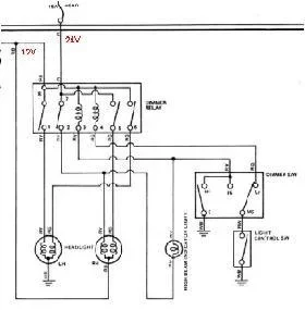
I inserted this from a 24V Canadian BJ40
24V center tap small.JPG

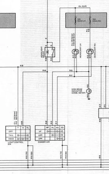
Into this from a 24V NON EUROPE HJ60 series wiring diagram
headlight_crop.jpg

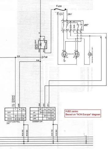
And the result is this:
12V-24V headlights HJ61.JPG

Note that in both diagrams Red/Yellow and Red/Green are the High/Low dimmer switch wires.
Both Cruisers use the same Dimmer Relay.
Only point of discussion is the High beam indicator light. In my diagram it's hooked up to the 12V High beam.
Can be wrong and must be to the 24V High beam. That, I can't figure out from Costa Rica.

Rudi

12V-24V headlights HJ61.JPG


24V center tap small.JPG


headlight_crop.jpg
 
Last edited:
Oh, so you mean to say that I could actually remove the dimmer relay, and then simply find out which wire goes to which wire ?
...and if I do that,I will have 24 volts to both headlight connectors??
Is it difficult to determine which wires belong to which wires???
I cant remember, but maybe if you remove both male and female connectors on the relay, you could simply match color to color????
And just get 24 volt bulbs??
...No more centre tap!!!?

Yes, that's what I mean. Disconnect the 8 pole dimmer relay and run new wires from headlights to the dimmer switch or even better install 2 relays at the same time so that the current goes directly from the battery, via the relay to the headlights instead of running trough the firewall and back.
There are some conditions before we can do that.
We have to do a few checks because by now it's clear to me that Mr.T did several modifications to this headlight circuit and did not document it.
I'm still wondering why the low beams are always "on" in Markthemenace's upgrade.

Rudi.
 
Should I assume that there will be some "abandoned" wires once this modification has been done?
 
Should I assume that there will be some "abandoned" wires once this modification has been done?

Yes,

Remove connector from dimmer relay. Leave relay where it is.
Remove the 3 pin sockets from the headlight bulbs. Put them in a plastic bag. Tape it closed. Fold double and tape them to the loom.
In other words.... leave them where they are. No need to peel them out.

More details later if you want to go this way.

Rudi
 
Last edited:
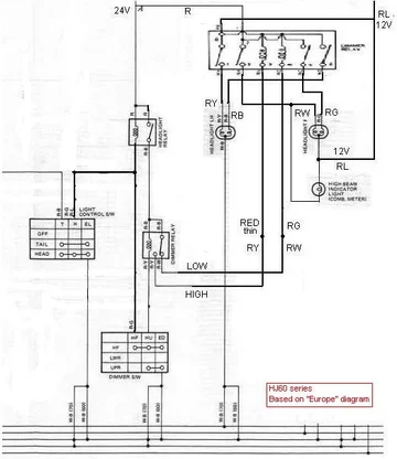
Here are 2 diagrams for the "evil tap" headlights in the HJ60 series.
I made 2 diagrams because I have no idea on which market model (Europe or non-Europe) Toyota made the changes.

The first one is based on the "non-Europe" diagram.
In this diagram the 12V dimmer relay is hooked up between 12V and ground.
This dimmer relay is controlled by the dimmer switch that connects to ground.
12V-24V based on non Europe diagram.JPG

The second one is based on the "Europe" diagram.
In this diagram the 12V dimmer relay is hooked up between 12V and 24V.
This dimmer relay is controlled by another (but now a 24V) dimmer relay which is controlled by the dimmer switch to ground.
I think that this version is the real one because the wiring colors match with the colors described in the thread from Mark: -► rewiring a stock HJ60's 12V headlights to 24V
12V-24V based on Europe diagram.JPG

One of these diagrams should fit your 60 series Cruiser.
Please let me know which one fits your cruiser.
The easiest way to figure out what you have is to look at your dimmer switch.
The "non-Europe" uses 4 wires (RW, RG, RY and WB) where the "Europe" uses 3 wires (RG, RY and WB).

Comments more then welcome,

Rudi

12V-24V based on non Europe diagram.JPG


12V-24V based on Europe diagram.JPG
 
Well, I understand that the cause of my problem is that my truck does have the 12 volt dimmer relay.
However, I,m not sure what to do?
Should I throw it in the scrap pile? ..Would I then probe test to determine which wires go from the light switch into the relay, and then just patch them into the headlight harnesses, thereby energising both bulb with 24 volts?, At which point I would simply install 24 volt bulbs?
 
had same issue

listen I battled my canadian 24v with 12v lights - it was give up
POW had it rewired to one battery

I ended up putting 24v lights - had to get new glass and light bulbs and 24v relays

in the end it was worth it thats my 2 cents

Kent
 
Well, I understand that the cause of my problem is that my truck does have the 12 volt dimmer relay.
However, I,m not sure what to do?
Should I throw it in the scrap pile? ..Would I then probe test to determine which wires go from the light switch into the relay, and then just patch them into the headlight harnesses, thereby energising both bulb with 24 volts?, At which point I would simply install 24 volt bulbs?

The plan is: disconnect the dimmer relay and the light bulbs. Leave that loom/harness where it is.
Buy one or two (your choice) in-line fuse holders, two 24V light bulbs, two 3 prong bulb sockets, two 24V relays, a handful of spade connectors and some wire.

Build a new headlight loom and we start from the unplugged connector.
final_modified.jpg

NOTE: the red lines in this diagram are not correct but we'll get there later.
This diagram was made while we (Mark and I) were experimenting how to hook it up.

Rudi

final_modified.jpg
 

Users who are viewing this thread

Back
Top Bottom