Help - Connection´s - stereo FZJ80

This site may earn a commission from merchant affiliate
links, including eBay, Amazon, Skimlinks, and others.

Joined
Apr 16, 2010
Threads
28
Messages
88
Location
Buenos Aires, Argentina
Website
gustavocherro.blogspot.com
Hi !!!!

I'm changing the radio to my FZJ80 1993
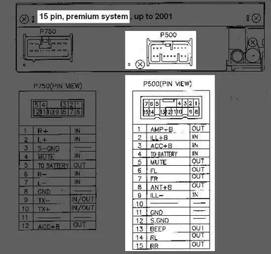
The original is a TOYOTA 56804 (see attach) and the connector has 15P

Has two speakers on the board, two in the front doors, two in the rear doors and a sub in the back

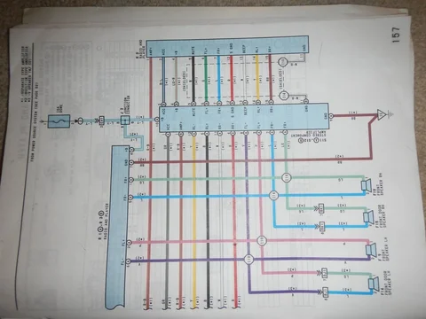
I need to find the diagram of connections to 15P connector (attach)
I tried to find it on the web, but none matches ......

Could anyone help ? I've tried looking everywhere and I can not find it .....

Thank´s !!!!!!

Stereo_Front.jpg

Stereo_Back.jpg
 
Not clear what you are doing. If replacing the stock radio (in picture) with an aftermarket radio there are two other connectors that you use and can buy a standard Toyota Metra adapter almost anywhere where they sell radios. This allows you to remove the worthless factory amp and makes the job simple.
 
Thank´s Phil !!!

Yes.... I´m replacing the stock radio with an aftermarket.... ( Alpine in this case )
The problem is, here in my country does have adaptors and I need to cut the wires and reconnect to the Alpine connector....

You know if my FZJ80 has an amplifier between the stereo and speakers ?

And one more.....

I live in Argentina and my native language is Spanish ..... I can communicate in English, but do not understand the abbreviations.

Could you tell me they mean?

ILL? is Lighting?
AMP ? is amplifier ?
S.GND? is Sound Ground?

and WTF !!!!! What is "+B"

Thanks Again !!!!!

All the best !!!!
 
If you have an amplifer, which I'm almost certain you do, it will be located to the right of the glovebox behind the dash speaker assuming you have a lefthand drive model. Remove the glovebox to gain access. The schematics posted above relate to that setup. The "radio and player" you have is shown vertically on the right of the diagram. With the Alpine you are basically installing the "radio and player" that shows as horizontal at the top.

The '''R2" connector is used for your current radio and connects to the amplifer. The outputs of the amplifier then go to the speakers.
For an aftermarket radio like the Alpine connectors "R1" and "R3" (also referenced as A and B) are used instead which go directly to the speakers. The Alpine should output enough power on its own to not require an amplifer for most guys. Even if you want aftermarket amplifers you wont use the Toyota amplifer or connections. Disconnect the connections to the amplier otherwise it will cause problems.

If you can't source the Metra harness adapter then you need to make your own with junkyard parts or tap directly into the R1 and R3 connectors .

There is also a subwoofer and amplifer located in the right-rear that should be disconnected as well. It is worthless and could cause problems.

ILL should be Lighting / Illumination

AMP is more than likely the amplifer remote turn-on. The radio supplies 12V to this wire when turned on. The is normally a blue wire on aftermarket radios to turn on amplifers and/or activate power antennas. The 93 and 94 model years do not need a power conection to the antenna from the radio.

S.GND would normaly mean Signal Ground

+B would be the battery positive
 
Hello,

Finally grabs my tester and with patiently I managed to connect my stereo.
The correct connection scheme is the image that Warrick gave me, but with some logical differences, since in this case did not put an original stereo.

Just changing the stereo, the audio system changed a lot in my truck .... a lot !!!
Definitely, the original stereo not have a good sound

Thank´s to all !!!!

Phil,

Really, your answer is brilliant !!!! thank you.

The only thing that varies is that if I use the "positive antenna" sends power to AMP only when I turn on the radio and not when listening to a CD or iPod, (at least in some stereos) so ..... in this case, I sent + from the ACC directly.

All the best....
harness1.jpg
 
I tried to simplify and understand the EWD stereo wiring diagram by showing the two cases, one with a separate main channels amp and one without, and merging it to one page. I also fixed what I think was an error with the front door speaker wire colors, changing color at the last segment. Disclaimer, I'm not sure what I've done is correct.

I'm still trying to figure out how the subwoofer signal works, since in either configuration the subwoofer amp uses the same connection as the rear door speakers. Does the OEM subwoofer actually take the amplified speaker level output as its input signal? Has anyone used the OEM harness to pass a line level subwoofer signal?

Case 1, With separate amp, R3 connected, R1 and R2 disconnected:
1738276129711.png


Case 2, No separate amp, R1 & R2 connected, R3 disconnected:
1738276196825.png
 
Yup again.

What wire did you use to send the line level signal? It can't share red, white, yellow, or black with the amplified speaker output, and the only other wires are power, trigger, and ground.
 
I'm running those four wires into a line-out converter. Then from the LOC, RCA jacks connect to the sub amp.
 

Users who are viewing this thread

Back
Top Bottom