Dual Battery Setups..? (1 Viewer)

This site may earn a commission from merchant affiliate
links, including eBay, Amazon, Skimlinks, and others.

Joined
Jan 13, 2007
Threads
28
Messages
105
Location
Orange, NSW
I'm looking to move to a dual battery setup; the second battery providing power for auxiliary systems. I want to keep everything standard on the car separate to any upgrades; thus any new systems (compressor, winch, camp lights, etc) will run solely from the second charge system.

I'm assuming this is a relatively common upgrade; i was wondering where the second battery and other associated paraphernalia is placed?

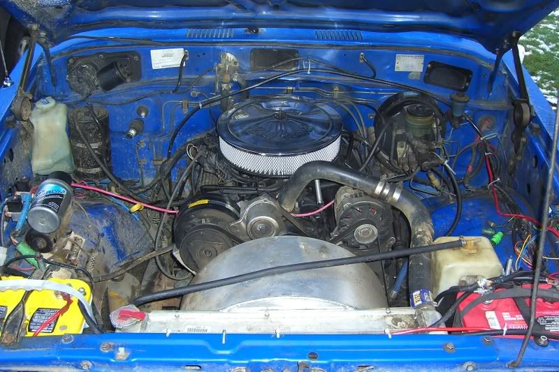
My main battery is on the left of the radiator when standing, facing the engine bay. On the right hand side there would be adequate space, if it were not for a small filter. I could (i assume), however, move this filter to place the 2nd battery there.

Any other places i can read up on this?

Cheers ~PHIL
 
A marine supply place would be a good place to get isolators and selector switches. I am a boat mechanic, and dual battery systems are VERY common to install in boats. I do a lot of 'em. I looked at both threads from the above post and there seemed to be some misunderstanding as to the purpose of the isolator. The isolator is intended to direct the needed charge to each battery. I.E., if you are listening to your stereo and have your camp lights on and kill your aux. battery, but your starting battery is good, the isolator will detect that and will direct most of your alternators charge to the dead battery, without over charging your live battery. It is "smart" so to speak. A simple selector switch would eliminate the batteries from drawing off of each other, but if you are not going to wire the aux battery into your starting system, there is not much of a need for a switch, other than to prevent your accessories from drawing the battery down when not in use. But if your are driving your rig regularly, then this would be of no concern.
 
If you go to the wreckers and buy another battery tray for a 60 you can locate it on the other side of the radiator. You will need to turn the support strap around and modify it a little. You will also need to relocate the overflow bottle.

As far as isolators go, try Redarc. There are heaps of others. Supercheap sell some too.
 
I used the painless kit from Man-a-fre:

CIMG0098.jpg
 
You can buy a second tray from several sources. It will bolt into existing holes. I took it a step farther and went with a second alt and have the aftermaket items completely seperated from the factory items. Works great.
 
On my truck, I actually had to drill one hole. It was the hole that secured the tray to the driver's fender well. And since I drilled the hole, I had to use a nut and washer as well as a bolt.
 
US spec fj60, dual batts, stainless trays, HJ60 overflow backet, Wranger dual battery set up, made all my own cables, Mean Green alt, very very pleased with this
38346535.jpg


and remember........the poster of the ? is in OZ......so his stuff is all backarsewards :D and its a 3F
 
That sure looks like a 2F to me.

US spec fj60, dual batts, stainless trays, HJ60 overflow backet, Wranger dual battery set up, made all my own cables, Mean Green alt, very very pleased with this
38346535.jpg


and remember........the poster of the ? is in OZ......so his stuff is all backarsewards :D and its a 3F
 
On a 3F, that raises another issue, at least on the US spec rigs. I am going thru this right now, and am still yet to resolve it, though I do have the parts to do. I installed my dual batt set up last weekend, using a standard battery isolator. However, the internally regulated ND alternator of the 3F, as opposed to the external one of the 2F, will not excite when hooked to the isolator. Therefore, I had no charge. As a short term fix, I hooked to alternator back up as original, and left the isolator wired to the alt, as well as my 2nd battery, but the main battery is recieving direct charge, not charging thru the isolator. The fix is a different style of isolator. I went with the Sure Power 12023A. It has a 4th post that you tap into the ignition feed on the back of the alternator, which will excite the alternator upon start up. I am sure there are numerous manufacturers of these style of isolators, I just went with the sure power because they are local, and I was able to get it at almost wholesale.
 
Last edited:
Dual battery systems with these "isolators" sometimes cause problems because there is a voltage drop across the diodes inside them that can cause the alternator regulator to either marginally or greatly fail trying to properly charge the battery (not usually a “smoke test” problem but simply results in an improper charging of the battery). At best, the battery charging will be reduced somewhat due to this voltage drop and at worst the battery will not be charged at all. Isolators are typically used in motor homes and cause many headaches there as well. Some electrical experts and motor home engineers get around this problem by using special regulators to account for the extra diodes (and voltage drops across them) in the line. I have avoided isolators in the past and instead use my simple charging method outlined below.

A cheap way of keeping the auxiliary battery charged is by connecting a 10 gage wire from one battery (+) to the (+) of the other battery via a 40 AMP (or so) DC breaker (available sometimes from used electronic or aircraft surplus vendor - as long as the voltage of the breaker is rated DC and greater than 12 volts, then only worry about the AMP rating). With this setup you will need to mount the DC breaker in a place where it can be easily reset, as it will trip from time to time. It should be flipped on when the engine is running and off when it is not. (Should also be flipped and left on if a battery maintainer is used during vehicle storage, assuming of course that the two batteries are of the same chemistry, i.e. lead/acid and the same construction vented/not/jel/etc.).

Note: You can also insert an AMP meter inline with the DC breaker that connects the batteries. This AMP gage shows the amount of current flowing into the AUX battery (a positive value indicates auxiliary battery is taking on a charge from the engine battery/alternator). The accessories can be wired on the DC Breaker side of the AMP meter as well and the amount of current flowing out of the battery will register as well (negative value indicates drain).

With this setup, the breaker will trip from time to time. When and why? This simple circuit is designed only for charging and is not designed to electrically “high current” connect the batteries during times of severe drain where one battery might need more current from the other. Examples of this would be, i.e. when the engine is starting and severely draining the regular battery or when the wench is grinding out the last ounce of power from the AUX battery and starts pulling from the other. Now since there is no isolator, the batteries are in effect connected together and current will try to flow through the small wire (relative to the temporary very high current load). In this situation one battery begins to pull from the other through the charging circuit. Once that pull reaches a current level over 40 amps it will trip the “charging” breaker. No harm done; just reset it once the excessive load has passed and the engine is running and time to start charging again. (Circuit breaker left on all the time the motor is running under normal circumstances.) Note: Maybe some built this circuit without the DC breaker and wonder why it smoked one day when one battery went low??? Now you know.

When you need to do things like allow the wench to “siphon” from the motor’s battery/alternator or allow a dead motor battery to “siphon” off the AUX battery, then another economical solution would be to place your jumper cables between the two sets of batteries until the need is satisfied (or something runs down you didn’t necessarily want to run down ). Of course the expensive solution to this need is to use the heavy duty solenoids that come with some auxiliary battery kits or that can be purchased at an auto parts store. These heavy duty solenoids can be thought of as a remotely controlled person connecting jumper cables to the two batteries (as long as you hold in the button or switch on the dash, of course).

Footnotes …..

- if rule is followed to keep breaker on only when engine is running, then breaker will logically not trip when engine is started
- forgetting and leaving the breaker on when the engine is not running causes both stock accessories and new auxiliary accessories to drain from both batteries at the same time (switching the breaker off when engine if off prevents this problem)
- I used a 60 AMP DC ammeter which is the kind that has a 0 in the center, -60 amps to the left and +60 amps to the right. The plus sign on the back of the ammeter goes to the (+) terminal of the auxiliary battery, the (-) side of the ammeter goes to either side of the DC breaker (and optionally to any accessories that use less than 40A max), the other side of the DC breaker goes to the (+) of the engine battery
- The winch would connect directly to the (+) side of the AUX battery (would smoke the AMP meter if you wired it there)
Good luck!
-

Wow. What a PITA. The voltage drop from an isolator is generally less than a volt, and won't cause any real problems. The isolators are solid state, very reliable, and fool proof. (I have installed many, with a single failure!!) There is no remembering to switch breakers, or flip switches, or wiggling your nose, or having to hook up cables and twinkle your toes and what not, and, as you noted, the batteries are automatically isolated to prevent one sucking the life out of the other, and the charge is distributed properly, so if you have one dead battery, and one fully (or near fully) charged battery, the alt. can charge the dead battery back to full without cooking the charged one.
:cheers:
What's a good source for driver side battery trays now that stainless trays no longer exists?

Dylan

You can put a stock tray on the drivers side. They are "ambidextrous", for lack of a better term. I actually got a good used one from shmukster here on mud from a rig he was parting out. The only difference between drivers and passenger side is the cross brace that runs from the inner fender down to the back side of the tray. I just fabbed my own, but I guess you can buy the bracket for a 24V diesel cruiser, and it will already be set up for the radiator bottle.
 
The stainless steel trays are NLA?

Getting back to the isolators, if you use elecronic instead of the diode type then you can get around the voltage drop issue. Dual batteries with an isolator is extremely common in Aus. and there are quite a few brands of electronic isolators.
 

Users who are viewing this thread

Back
Top Bottom