Well, my 1986 FJ60 with a G & S Cruisers (thanks Sheldon) 12H-T is now "officially" on the road - California DMV checked to see that it is in fact a Diesel and that was that. FWIW, this FJ60 is a previously California registered truck for the last 340,000 miles, so this was just an engine/transmission swap.
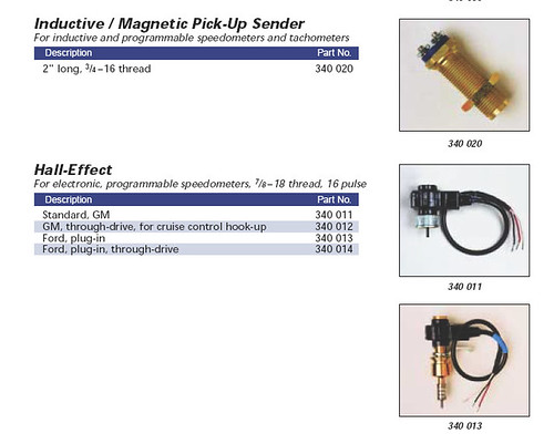
Now for the TACH: Is it possible to use the existing FJ60 tach and attach it somehow to the sender unit on the HF55 trans/bellhousing that came with the 12H-T ?
I'll get some video of this truck up on youtube in a few weeks. Runs great with new OME suspension, rebuilt front end, rebuilt transfer case, BFG AT 33 x 10.5 on 8x15 rims, 3 inch exhaust and AeroTurbine. Toggle switch for glow screen. It is now dual batteries setup to charge together but operate separately via a selector switch.
So the tach is a problem, plus gotta hook up the water temp gauge, alt charging gauge, and plumb in the water separator to the fuel feed line.
Throttle is a bit twitchy, but fine for road use. Really looking forward to getting in the woods with this after a few hundred miles of local travel to shakedown the rig.
Thanks in advance for any tips with the tachometer hookup.