Navigation
Install the app
How to install the app on iOS
Follow along with the video below to see how to install our site as a web app on your home screen.
Note: This feature may not be available in some browsers.
More options
You are using an out of date browser. It may not display this or other websites correctly.
You should upgrade or use an alternative browser.
You should upgrade or use an alternative browser.
x (1 Viewer)
- Thread starter Lil'John
- Start date
This site may earn a commission from merchant affiliate
links, including eBay, Amazon, Skimlinks, and others.
More options
Who Replied?Want a plug? I think I have one. <<<<<<<<Free
 <<<<<<<<Free
Does that particular switch have the "convoy" setting where only the rear tail lights illuminate?
I do not see any screws. this is an early light switch? i thought the early headlamp switches rotated instead of pulling out? 
place
on the dash on the left of the steering wheel
on the dash on the left of the steering wheel
This sounds like a job for COOLERMAN!!!!!!
The lightswitch is for a [FONT=arial, helvetica]68-9/71 cruiser.
I'm not sure about a convoy mode... but it is a two step pull switch. First step turns on the marker lights. Full pull turns on the head lights.
[/FONT]
I do not see any screws. this is an early light switch? i thought the early headlamp switches rotated instead of pulling out?
The early rotary switches had the convoy mode, with a certain position of the switch, only the rear lights came on. That ended with the push-pull switch.
I know it takes some time but I usually get some wire to a batt. and a light tester, just start testing in the different positions.
Want a plug? I think I have one.<<<<<<<<Free
I've actually got two plugs that are keyed correctly(heater I think) along with wires... just no idea what goes where.
One is going to be used for headlights... the other will be used for fog lights
I meant the RIGHT PLUG for the headlight switch....the one that should have the correct color codes on it
If you have it, life would be nicer with the wiring
Okay, I'll go look and see.....
Sorry about that, I forgot!
dgangle
total rice
John,
Not a direct answer to your question but what I did on my later model headlight switch was to take the switch out, lay it on the bench and use a multimeter in the 'continuity mode' to determine what was what. One could use the resistance function to do the same thing, I just like the little beeps my Fluke offers instead of interpreting a reading of resistance. Of course an understanding of what each position of the switch should provide was helpful to me.
Hope this is not more confusing but of use to you.
dgangle
total rice
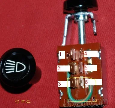
Looking at the picture further, 2or 5 should be 12V in, 3 & 6 should be tail/dash and 1 & 4 should be headlights. Without having it in front of me with a multimeter that's as good as I can surmise. You could also bend the small locking tabs by terminals 1/4 & 3/6 to open it up to see what's going on inside. As the shaft/knob is pulled, an interior conductor will slide making contact with different terminals to direct the voltage to the various terminals/circuits.
get your multimeter and open the switch carefully. It's pretty simple/ingenious.
get your multimeter and open the switch carefully. It's pretty simple/ingenious.
dgangle
total rice
dgangle
total rice
dgangle, I was going to use that as a last resort
The difficult part is not knowing which wire is the power wire.
I'd put money on 2 and/or 5
take it apart carefully and put it back the same. Won't hurt a thing. Based on stuff you've built/fab'd this is a .00000000001
 job.
job.dgangle
total rice
Forget what I said before regarding the terminals. see that soldered jumper between 4 & 5? That is key.
2 power in
1 headlights out
4 tail/dash
3 & 6 uncertain. maybe the 'convoy' (tail lights only) ??????
5 nothing
2 power in
1 headlights out
4 tail/dash
3 & 6 uncertain. maybe the 'convoy' (tail lights only) ??????
5 nothing
dgangle
total rice
good. while my answers may not have been exact, hope my reasoning helped you to some avail.
dgangle
total rice
that's not agony, it's FUN! Takes all types, huh?
Do you have/can get a wiring diagram for the vehicle?
Do you have/can get a wiring diagram for the vehicle?
Coolerman
SILVER Star
- Joined
- Jan 5, 2004
- Threads
- 142
- Messages
- 6,765
- Location
- Paint Lick, KY
- Website
- www.globalsoftware-inc.com
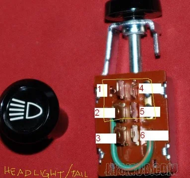
This pic might help a bit.
If I can remember, tonight I'll verify the contacts but just looking at the schematic it works as follows:
Park position ties Terminal 5 (R = +12V) to Terminal 2 (G = Park Lights) and Terminal 6 (RB = Gauge Lights) via the jumper on the switch turning on Park Lights and dash lights.
Headlight position does all the above and adds Terminal 1 (RW = Dimmer switch) turning on the headlights.
Users who are viewing this thread
Total: 2 (members: 0, guests: 2)


