Budget H diesel turbo buildup

This site may earn a commission from merchant affiliate
links, including eBay, Amazon, Skimlinks, and others.

RufusTheDufus

SILVER Star
Joined
Jan 9, 2008
Threads
180
Messages
2,818
Location
Moronville, ME
Yet another turbo buildup thread.

I'm doing a log manifold for the H diesel in my 1980 HJ45 Troopy. There's really not much available out there for adding a turbo to an H so I figured I'd just do one myself. I know it's not the ideal engine for a turbo but I already have it so I might as well use it.

I had to replace the pistons so I did a valve job at the same time. (The replacement pre-cups are still on order.) It's the perfect time to add a turbo.

The only "special" thing about my buildup is a little fun with Solidworks designing an exhaust manifold mounting flange. I had them laser cut by Laser Cutting Services in Oregon.

h-turbo-buildup-1.jpg


The manifold will be made from 2" square 316L stainless. It's maybe not the ideal material but it's relatively cheap and easy to work with.

I'm guessing the total cost of materials for the project will be $450 to $500. That's a pretty cheap turbo setup if it actually works.

For more pictures and details see my blog at Parts is Parts | Rufus The Doofus

I'll also post more photos and updates here as I make progress.
 
Nice work going the DIY turbo install path, dude.

Should be a good thread, this!

Please, do go on....
 
I'll be watching this one with interest, I know a few years ago Denco here in Australia offered a turbo kit for the H - never tried it though. BTW, as an aside, anyone manage to bung a power steering pump onto one of the H motor successfully?
 
Come on, post up the solidworks shots.:)
 
The solidworks shots are pretty boring. They look exactly like the part in my hand above.

I didn't have the holes for the studs laser cut. The 2" square tubing is a tight fit between the studs. I'm going to drill the holes after welding the tube to the flange.

This photo will illustrate that more clearly.

h-turbo-buildup-4.jpg


The general plan at the moment is to cut 1 inch stubs of tubing and weld them to the flanges. A short piece of tubing will allow me to weld both the inside and the outside edges. When that's done I'll drill the holes and bolt the stubs to the head. I'll use their placement to mark up the long section of tube so I know where to cut ports.

Next I'll TIG the whole thing up and weld in block-off plates on the end of the long tube. Then I'll figure out where the 1/2" thick flange will go for the turbo. It should be fairly easy to pick a spot to place the turbo. There's lots of room on that side of the engine and it should be fairly easy to route the intercooler plumbing under the alternator too.

I'm thinking that I will need to gusset the stub-to-log welds. I haven't figured out how I will tackle that yet. I'm also wondering if I should double up the material on the side of the tubing with the manufacturing weld? You can see the weld on the inside of the tube in this photo. It's not visible from the outside.

h-turbo-buildup-3.jpg


I have no idea if a welded tube like this will eventually crack from thermal cycles.
 
With the tube that size and the studs being a bit short on space do you still have enough room for a ringspanner or socket to fit on the nut allowing for the weld chamfer or are you going to use set screws? It is difficult to see from the picture you posted. The stainless cuts are really cool, cheers.
 
I should have enough room. I'll printed a 1:1 sized part on paper and placed a gasket and tube on it. I'll scan it later today just for illustrative purposes. It's tight but it should fit. I may need to drill into the weld chamfer a small amount. I plan to build up the weld in that area on the inside of the tube to compensate for the drilled area.
 
flange interference

I traced the flange and the outside edge of the tubing. It's tight but I should be able to make it work.

Before I weld the stubs to the flange I may notch the tubing slightly and then build up the weld on the inner edge in those areas.


h-exhaust-flange-notes.jpg
 
I traced the flange and the outside edge of the tubing. It's tight but I should be able to make it work.

Before I weld the stubs to the flange I may notch the tubing slightly and then build up the weld on the inner edge in those areas.


h-exhaust-flange-notes.jpg

Instead of notching you can dimple the tube in a bit.
 
That crossed my mind too.

A friend of mine has a machine shop here locally. I was going to ask him what he recommended. I wouldn't be surprised if he has a tool to easily dimple the tube. He builds a lot of exo-roll cages for ski mountain groomers so he's got just about every tool you can think of related to tubing fab work.
 
With the tube that size and the studs being a bit short on space do you still have enough room for a ringspanner or socket to fit on the nut allowing for the weld chamfer or are you going to use set screws? It is difficult to see from the picture you posted. The stainless cuts are really cool, cheers.

Is it possible to use cap screws instead of studs and nuts?
It reduces the needed clearance by a huge amount, but sometimes they just don't fit.
 
Is it possible to use cap screws instead of studs and nuts?
It reduces the needed clearance by a huge amount, but sometimes they just don't fit.

Cheers Dougal, Pretty sure you used more correct terminology than me :o. I remember they were classed as screws because they had much finer tolerances than bolts. But you use an Allen wrench to tighten them, no need for external fitment of a ring or socket. These exhaust manifold bolts only need something like 15/20 ft/lbs, have to look it up. The last nuts on the 2H/HJ75 are a pain to do up from memory, early model may have more room. cheers:beer::beer:
 
PM sent Juha.

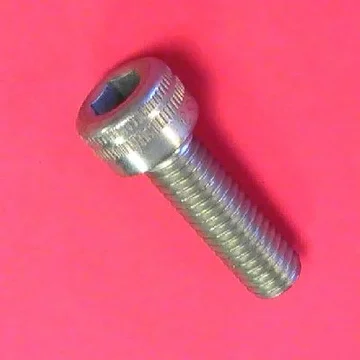
The official name for those screws are socket head cap screws, I'm 99.9% sure, they're good as long as they're good quality and you use good allen keys/inhex sockets.:)
 
PM sent Juha.

The official name for those screws are socket head cap screws, I'm 99.9% sure, they're good as long as they're good quality and you use good allen keys/inhex sockets.:)

:cool::beer::beer::beer::beer::beer::beer::beer::beer::beer::beer:
Thank Mate, well done. Thought someone would know what I was on about. :idea:It is called C.R.A.F.T.= can't remember a flaming thing.::hillbilly:
 
I hadn't thought of using allen head cap screws. That's a great idea. I'll need to source some metric ones. Problem solved. I hope to get to welding and drilling this weekend.
 
SHCS

PM sent Juha.

The official name for those screws are socket head cap screws, I'm 99.9% sure, they're good as long as they're good quality and you use good allen keys/inhex sockets.:)

Spot on, SHCS the acronym.

SHCS_M.webp

They are used all the time on downhole oil tools, due mainly to spacial constraints. And, yes, make sure you use good allen keys, otherwise thay can be easy to strip. Otherwise they are very strong, and I think will be perfect for the job.

EDIT:

Oh, as long as you have a long enough allen key to get into the cap between the manifold.
SHCS_M.webp
 
Spot on, SHCS the acronym.

Most cap screws are grade 12.9-14.9. Much stronger than your average hex box.
Other flavours include:
Button head cap screw, with a rounded head and smaller hex.
Low head cap screw, like a normal socket head but shorter head.
Flat head cap screw (countersunk).

Just make sure to use a decent exhaust paint on them. The factory black finish has no corrosion protection.
 

Users who are viewing this thread

Back
Top Bottom