Builds Blender, My LX450/FZJ80 + FJ45esk + GM + Land Rover crazy concoction (1 Viewer)

This site may earn a commission from merchant affiliate
links, including eBay, Amazon, Skimlinks, and others.


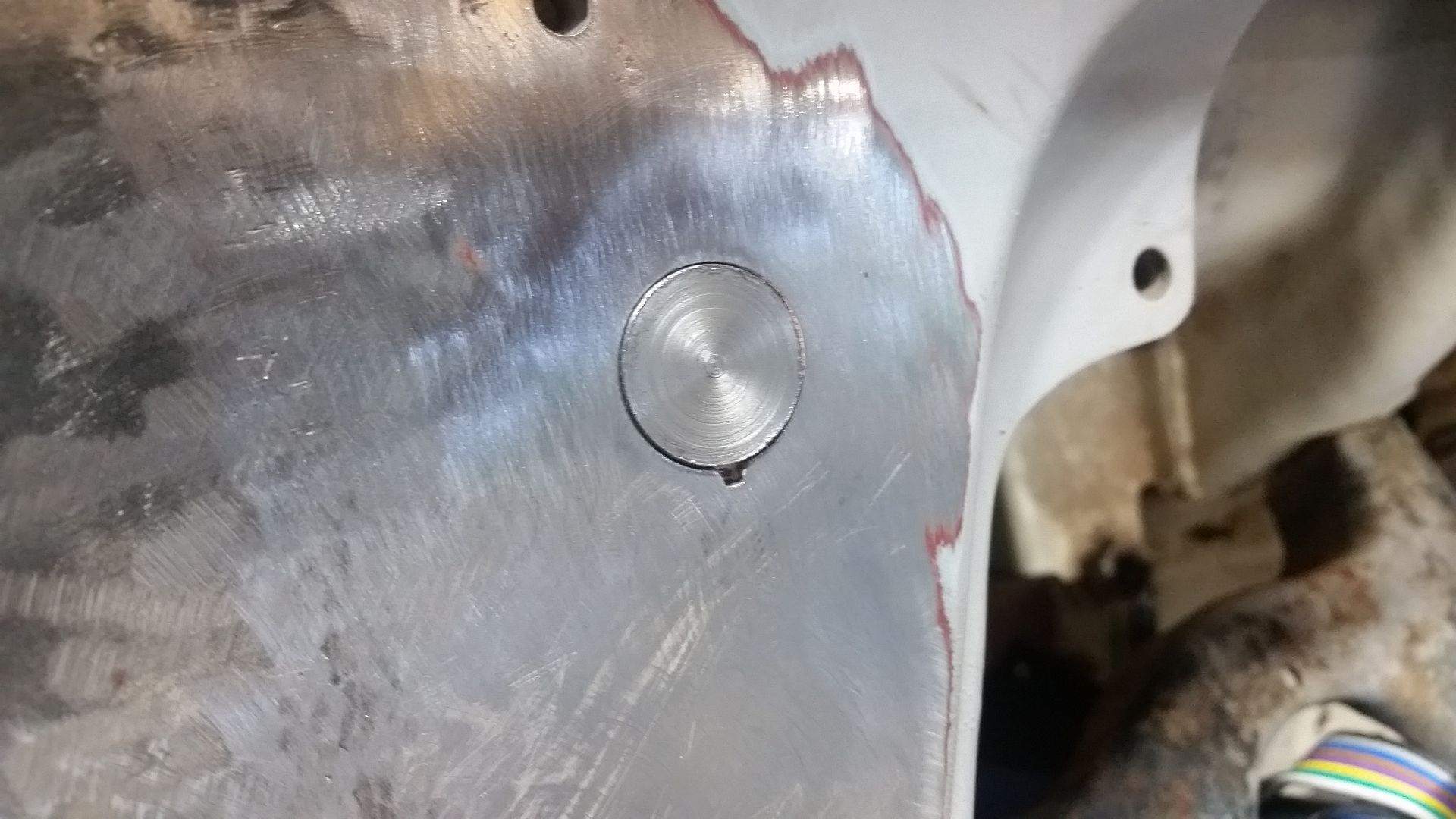
For round holes I have found it easiest to use some round bar stock that is the right diameter for the hole. I can turn the end of a short section of bar to fit exactly on the lathe if needed. You can also dill the holes out to the next stock size if you don't want to turn something, or if the hole is an odd punched shape. To make the proper thickness of material I slice off section in my bandsaw. With a little setup I can get .040 to .060 discs which are great for most sheetmetal patches.


To do this I set the little stop on the HF saw. The only real issue is when you need to cut off some stock once you set the stop to make more patches. For this, I just insert a scrap of bar stock under the part I need to cut off. This gets the part above the stop so you can maintain the fine/thin setting on the stop and not have to set it up again.
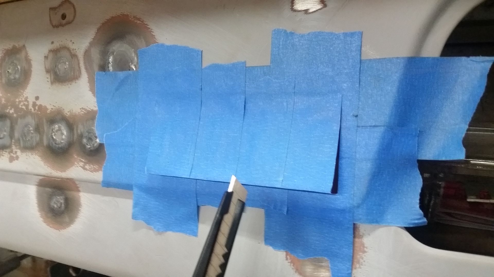


If you need to make a pattern for a large, or odd, hole coat the area in two layers of masking tape. If you can press from back all the better. Then cut out the shape you need with the thinnest razor edge you have. That template can then be stuck directly onto the metal you need to cut the template out of.


When you are done you get a patch that should fits like this that takes very little after cut cleanup.


This is what the dash looked like with all the holes welded shut prior to clean up. Lately, I am really liking the TIG welder for stuff like this other than having to be all out of position and needing 3 limbs to do everything. I ended up having to set the pedal on a milk crate to get it into a position I could run with my foot hanging out the door.

I still have a little more clean up work to do on things, but overall I am pretty happy.
 
I borrowed your masking tape template idea recently to make a 3D template of a mandrel bend I was trying to section to fit against another for a turbo dump pipe. :cheers:
After stuffing up two bends at $45 a throw, I wrapped one with about 30 layers of masking tape in multiple directions, then marked out and cut a rough shape before trimming my 3D template for a perfect fit. Worked an absolute treat:cheers:
I rubbed some flour on the adhesive to stop it being sticky while I was test fitting. My son thinks I'm nuts
IMG_20170430_124119.jpg
:lol:
IMG_20170422_161044.jpg
IMG_20170423_122729.jpg
 
Time to move onto something pretty challenging, the construction of a custom aluminum top panel. The idea is that the top panel will bolt onto the halo cage structure and be generally shaped to follow the curve of the windshield frame without adding much additional height to the vehicle if any....

To move forward I had to do a few things....


I needed to add this flat bar into the door pocket offset of the halo. This is set in plane with the top of the halo and fills the gap to the windshield frame also. There will be another sheetmetal section to this that will provide the surface for the door sealing, but I don't need that just yet. This bar basically helps set the offset for the drip rails that will go around the edge of the top.


These bars also allowed me to figure out where the halo intersects the windshield frame. On the stock FJ40 the door surround bolted to that hood and the top panel as about 1" above the horizontal black line. That little section of the corner of the windshield frame needs to be trimmed out of the way to make the shape of the top more uniform and at a smoother radius.

This change is kinda like pulling down your hat a little further. It should make the chassis look like it is chopped about 1"....but without having to chop the windshield. I still probably should have chopped the windshield frame down, but I really didn't want to.....


I made up these little test bends out of 1/8" 5052_H32 for the drip rails. I am going to try and retain a factory looking 1970s-ish drip rail around the sides and back of the top panel. My hope is that this will keep the water out of the cabin if the vehicle is caught with the rear panels and upper section of the door removed. It also makes the outer edge of the bend much stronger.


The inside of the drip rail section has a flange that will bolt to the inside of the halo. I will be using some 8mm rivet nuts in the cage structure to attach everything. It should be fairly easy to remove the top panel if needed, but I plan on just leaving it in place generally. It will be painted a different color than the body however so it will be nice to have it be a separate piece.
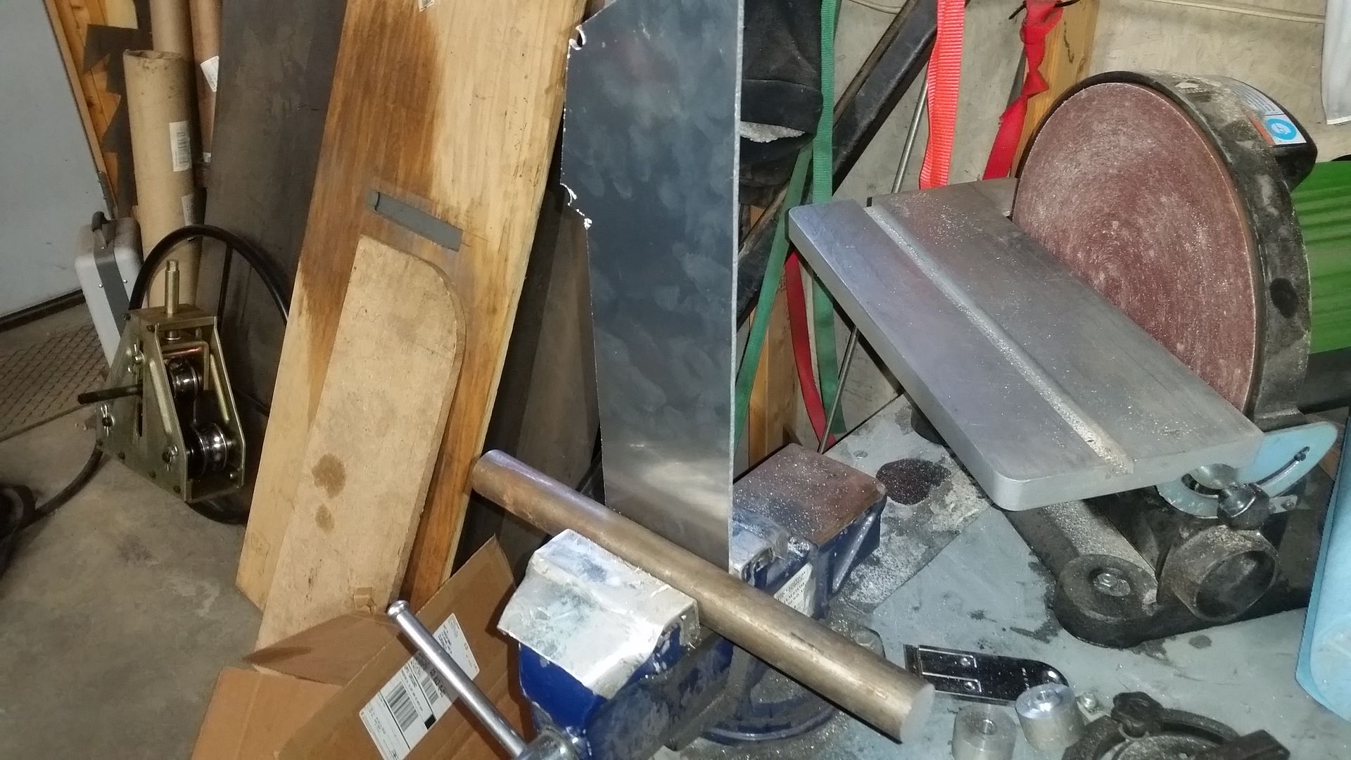


This is the section that sits on the top of the halo ( and that door bar ). This is what the other parts of the top will weld onto....


The rear channel was done much the same way, but does not have to extend over the door opening offset. The distance from the edge to rail is the same to keep things uniform on the exterior.


The outer drip rail flange needed to be formed with more length and then trimmed down to form the shape I wanted. I am basically trimming the flange off right after the bend. I did this by marking the offset using the width of the marker body. This makes it quick and easy to run over an entire panel, or multiple panels later, so they can all be trimmed the same.


Once I had a plan I needed to stop by the aluminum store....and to get some wood which will come in handy later.
 
Onto the next part of the top project.


Once I had the test bends done I could move onto making full size parts. That new press brake I made a few month back sure does come in handy for it's size/weight. The only real hitch is that the steel dies mark up aluminum a little more than I would like. Those marks buffed out for the most part. This aluminum is 1/8" thick so there is a little margin to play with. I found that and 80 grit sanding disc followed by a red scotch pad seems to give a pretty good surface finish.


I didn't want to cut a length wise section out of my new sheets of aluminum. I ended up having to add a 10" section to the rear rail in order to have enough length to span the width of the body. The ends will be trimmed off, but I wanted a bit of extra to play with...

I tig welded both sides and dressed it all back down. I don't think it turned out half bad.


The next challenge was to trim down the trip rail flange like I did on my test part. I ended up pulling the saw away from the wall in order to be able to feed the longest 58" channel through. I even had to pull the last 10" of the parts from the back side of the saw to keep things balanced since I couldn't round up a helper.


The next step was to develop a template in order to trim the drip rails to fit around the A-pillar spreader up to the front edge of the windshield frame. I used a bit of chipboard, a ruler, and some offset geometry to figure this out. Once I was happy with the fit I used that template to trim the aluminum parts.


After much trimming and fitting the rails where clamped onto the halo and welded together with the TIG. The rear corner will be trimmed to match the radius of the halo bars and the drip rail added back in eventually. I'm not sure when the right time to do that will be.

Now I need to think about how I am going to form the curved top panel shape. I think I am going to make a new die for the press.....
 
Shop tip. (maybe) ;)
Add a couple of layers of duct tape to sheet metal at folds to prevent marking the surface in the press.

I had shoplifters installing mirror polished decorative stainless steel on a project last week. The stainless had two layers of protective film on it to stop the bender marking it.
 
Phase one of making the top.


I don't know about this non-metallic stuff. It's all warm and full of life. Ew.
These ribs will come in handy to help define the shape of the main top panel to the same arch as the top of the windshield.


I also knocked up a new top die for my experimental project with a larger radius. This is 1" heavy wall tubing for a 1/2" radius. With the way the top is designed I can weld anything to a 1" thick tang and it can be held in the top of the press by the clamp plates.


The front wall of the top will wrap around the front of the windshield frame where there is two 6mm fasteners stock. I will be using the spine on the top of the windshield frame for a bulb seal I think.


The rear wall of the top is at the same angle as the front windshield part, but also has to transition around the rear corners. I had to do this in a few parts. This will also be trimmed to the top profile using the wooden bucks as a guide.


There was a slight learning curve with how to form the top panels. The 1st test part I did I bent from the tight end to the loose end....which would be 6 towards 1 in this pic. That just didn't work as well as I wanted. I ended up reversing that so I started on the 1 side and bent things tighter and tighter towards the edge of the panel. This ended up working a lot better.


This is what the top panels looked like after a little tweaking of the press brake. I ended up needing to add a decent amount of top truss tension to the press to keep the bend angle consistent across length of the part. 43" of 1/8" 5052-H32 aluminum does cause a workout on the top truss design.

This bend is basically a bump-formed shape where the radius is variable or larger than the top die radius.


Now to spend the next week trimming all this stuff to fit and tacking it into an assembly....

I will follow this up with some shop tip stuff. Photobucket is giving me fits.
 
Mad skills
 
I don't know about this non-metallic stuff. It's all warm and full of life. Ew.

Missed this bit in a few posts back, but got a good laugh reading it just now. Keep it up man, loving it.

Any detail shots of the finished roof, particularly of the inside?
 
Missed this bit in a few posts back, but got a good laugh reading it just now. Keep it up man, loving it.

Any detail shots of the finished roof, particularly of the inside?

Thank you. I try and keep it light....

Here are a few pics of the inside.


If there is anything specific you are wondering about let me know. The C to A spreader is still missing. I will add that next time I have to take the top off. It is just going to be a section of 1.5 dom with with a little bend at the back to help it hug the roof. I want it as close to the roof skin as practical for headroom. I can also add some closed cell foam between the spreader and top to eliminate a little of the span of the top panel to get the noise down. The top is 1/8" 5052 aluminum so it really is pretty sturdy and quiet. I will also be spraying the underside with some heat/sound stuff before paint.....
 
Keep going, love this build...
 
Lets try to get back into the mini-update habit.


When I was messing around in the cabin space I decided to mount a heater. I decided to use the Summit Universal 30,000btu unit.

Summit Racing® Automotive Heaters SUM-991102-1

It is a nice little unit. It comes with rotary switch for the fan control. For $150 not a bad little unit.

I fought back and forth on where to mount it. I REALLY want to be able to tie into the factory defrost ducting AND have floor heat. I will be dedicating one output to each function. I am thinking about making some kind of tube duct system to do that, something that would look kind older/retro.
 
Next up is going to be front fenders....


Here is the chip board mock-up. I had to try a few different things to make it look NOT like a Jeep. I think the little front dip 'bill' helps that. These fenders are pretty small overall to stay out of the way. They only stick out about 1" past the body. The tops are also tapered to match the hood profile.


Here is the start of the fender in 1/8" 5052-H32 aluminum. The majority of the fender is made in two parts. These will bolt onto the modified grill shell and the rear lower flange of the tub/cowl.

I used my custom press brake to bend everything so far.

The lip flanges are about 1" wide and 22 degrees. That really stiffened up the panel and gave it a bit of style.


I handy way to hold aluminum panels together. The tab is bent from scrap to fit the angle you need. These really make alignment much easier.


Drilling holes with a step bit before cutting out inside corners makes it possible to eliminate sharp 90 inside corners that may be weak points.


Welding the two big parts together on the vehicle was fun being all out of position and out of practice with the TIG.

I also marked ( from behind with a welding filler wire pick) all the mounting holes prior to pulling things apart.

Once welded and drilled for mounting I will trim the front for the 'bill' lip features.....
 
Amazing, really like the front corner, that is slick,

Did you bend the outer edge like the cardboard?? And did you get a deal on the aluminum?

Really like the roof and fenders but that wasnt cheep...
 
Amazing, really like the front corner, that is slick,

Did you bend the outer edge like the cardboard?? And did you get a deal on the aluminum?

Really like the roof and fenders but that wasnt cheep...

Yes. The outer edge has a 1.13 flange at about 23 degrees of bend. Because the shallow bend it is a pretty soft radius that doesn't show up in pictures.

The aluminum isn't free. I think I paid about 200-300 bucks for a big 4x12 sheet. The fenders will about clean me out. I will have to buy another sheet(s) to do the doors, bed, , tailgate, and upper rear panels. The bed floor and belly pan will also be thicker flat sheets of aluminum. I like working in aluminum a lot more than I thought I would. Hopefully in the end it pays off and the overall weight of the vehicle is lower. I am hopping for sub 4000lbs.
 
Part 3 of 4 for the front fender....


It felt like more of a step backwards cutting out a big chunk of my new fender. I was also able to drill the mounting holes so the fender holds itself in place! Mini-Win.

Forming this little panel wasn't too bad. I just used a drop of material that was a bit big to whittle down to the right shape. That is always easier than adding material.


Clamping the little panel into place for tack welding was the hardest part I think....


This was my super complicated bending jig for the radius I needed....
 

Users who are viewing this thread

Back
Top Bottom