BJ40 - no headlights

This site may earn a commission from merchant affiliate
links, including eBay, Amazon, Skimlinks, and others.

Still makes not much sense to me. If that fusible link is indeed a "shunt" then if it blows it will send all the current through your gauge. Remember a shunt is in parallel not series.

Which is exactly why they put two 5 A fuses there Alex - One in each of the wires to my ammeter.
 
Ok, so there are two 5A fuses plus another in parallel for a shunt?

You will have to show me the circuit diagram or draw it up as it does not make sense.
 
If its like this (81 24V BJ40) then they are simply inline fuses and do nothing more than protect the circuit.
 
Last edited:
If its like this (81 24V BJ40) then they are simply inline fuses and do nothing more than protect the circuit.

Ah. I see I don't need to send you any diagrams now because you already have access Alex.

Yes. My ammeter (and Craig's) is wired exactly like that.

Toyota appears to have thought that diagram you call a "24V diagram" is suitable for everyone - including those of us with only 12V battery/charging systems. (Take a look at how they depict the battery and you should see both 12V and 24V set-ups drawn there.) ..... But the inclusion of 24V wiring - particularly relating to the headlights and "dimmers" (where no alternative 12V wiring is shown) makes the diagram "rather much of a nonsense" for a 12V vehicle.

Not sure why you say those fuses "do nothing more than protect the circuit" (which implys to me that you think they won't protect the ammeter internals should the monitored fusible-link decide to blow). I guess you are saying that the ammeter coils must be "finer" than the fusewire and will therefore blow before either 5A fuse.

Perhaps owners who've blown their fusible link can chime in and tell us whether it resulted in "a blown 5A fuse as well" or "a blown ammeter as well".

:cheers:

PS. Interesting discussion!:)
 
:meh:

That's the same as my setup and I also have that fusible link.
My gauge is just straight through with no resistance, so it doesn't get hot. The reason that I say the fuses protect the circuit is because the gauge is just a solid piece of brass.
 
Here's something I found on this type of gauge.
The term "Zero Magnet" makes it sound like some special sort of magnet - it should have been called "Zeroing Magnet". All it does is keep the needle centered when there is no current flowing through.
Pantera Ammeter
 
:meh:

That's the same as my setup and I also have that fusible link.
My gauge is just straight through with no resistance, so it doesn't get hot. The reason that I say the fuses protect the circuit is because the gauge is just a solid piece of brass.

I'm totally lost now :frown: :eek: :lol:

I admit I've never had my ammeter gauge apart.

I assumed your picture was of an older-style gauge in which the full current passes (rather than mine where "only-a-sample-current" flows).

But now you're saying that you have the fusible link and twin 5A fuses (in a 1977 BJ40) with that ammeter (that is pictured above) and that it operates perfectly off "a tiny sample current".

So how does this TINY current "produce magnetic field and move your needle" when passing through all that brass I see in your gauge?

:cheers:

Edit: Just read your post directly above - That link is informative but doesn't help me understand what's going on here. It still makes me think you have an "old-style gauge" in "new style wiring".
That info says you should have FULL current through all that brass (in order to create sufficient magnetic field) and not just a TINY SAMPLE CURRENT.

I've got to go outside now and do REAL work for a while (and get off the damned computer). But I am enjoying this and will be back trying to figure it all out!!! (My mind will no doubt remain on topic while I'm outside.)
 
Last edited:
I'm sure Craig won't mind us completely hijacking his thread now that he has his headlight problem fixed Alex :D

I've sent you a PM just to double-check that I've correctly understood what you've been saying so far about your ammeter and ammeter circuitry. (I'm still baffled - but then that seems to be a common state-of-mind for me these days. :hillbilly:)

And I thought it a good idea to throw in the wiring diagram I modified from the FSM one (some time back) - purely to show the exact wiring on my own 1979 BJ40:

WiringCharging.webp

(I find it easy to read the way I've drawn it and it shows exactly how my ammeter is wired. - The internals of the voltage regulator may be incorrect however - And I'd be grateful for advice there if anyone has any. Etc)
WiringCharging.webp
 
As you have noticed you are not the only one that tends to get baffled :lol: You know it would be wonderful (and less mind-bending) to have the correct wiring diagrams for our specific vehicles :mad:
 
Righty-ho. Without seeing your cruiser in person - I don't think I can get any further on understanding exactly what you have there Rockcrawler/Alex. But as far as I can see, that -30 - 0 - +30 ammeter you pictured is "old-style" (as it should be for a 1977 model too). And the site you provide the link to (unless I've read it wrong - which is quite possible :D) says it has a "Pantera Veglia" movement that requires ALL THE CURRENT to pass through. .... So I gotta leave it there......

Meanwhile. I've been doing quite a bit of research on our ammeters and fusible links, the results of which may be useful to post here.

Firstly - for Craigwanderer's benifit - gibgoaz 8 made an interesting post in this thread:
https://forum.ih8mud.com/40-55-series-tech/269245-fuible-link-shunt.html

Here he says he replaced his fusible link with a 30A fuse and it blew. So he went up to using a 40A. So on that basis - it might not pay to go below your 20A rating Craig - And it might actually pay to hold a bigger fuse as a spare. (20A definitely is too low considering you have a 35A alternator there!)

Now--- my -50 - 0 - +50 ammeter (that uses a fusible link as an external shunt-resistor) is part number 83610-60023.

Other ammeters (through which all current passes - rather than "just a sample current") are shown in this EPC printout:

ammetersEPC.webp

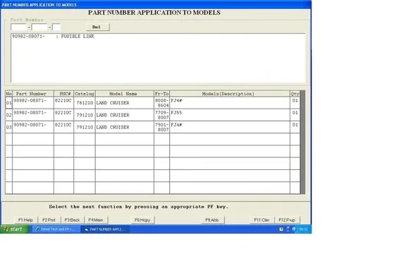
And my "fusible link pair" are listed under part number 90982-08101 (while your typical FJ40 is different at 90982-08071

BJ40fusible.webp

FJ40fusible.webp

:cheers:
ammetersEPC.webp
BJ40fusible.webp
FJ40fusible.webp
 
Last edited:
Oh. Here's another printout which better shows the extent of use of my later-style -50 - 0 - +50 "external shunt" ammeter:

50 0 50ammeter.webp
50 0 50ammeter.webp
 
Awesome info guys! I might even end up having a fixed amp meter after all of this. At the moment I'm using a plug-in Supercheap Auto 12V double adapter with a battery level indicator - not ideal.

Cheers!
 

Users who are viewing this thread

Back
Top Bottom