Adding Fused Circuits the Toyota Way (1 Viewer)

This site may earn a commission from merchant affiliate
links, including eBay, Amazon, Skimlinks, and others.

TrickyT

Hate that mud...
Joined
Apr 1, 2006
Threads
19
Messages
1,491
Location
Mill Valley, CA
On my FJ Cruiser I noticed a bunch of unused fuse positions in the interior DS fuse block. So when it came time to add a couple fused circuits for my refrigerator and seat heaters and I searched for threads on how to do this, I was surprised that apparently no one has ever directly used these pre-wired circuits before. Now Bussmann and Littelfuse both make "add-a-fuse" kits you can buy, but this approach blocks other existing fuse positions and thus prevents you from getting at those fuses or limits how many circuits you can add (see photo below).

I took a different approach. I used connector terminals, either ones you buy from Toyota (p/n 82998-12340) or the bare terminals you crimp onto wires yourself made by Sumitomo Electronics (see links below), and just added these to the empty positions in the terminal housing for the particular fuse position I wanted to use. It's a little more complicated than using an "add-a-fuse" kit because you have to access the needed connector and insert the terminals, but if you've ever worked with Toyota connector housings before you know this is pretty easy to do.

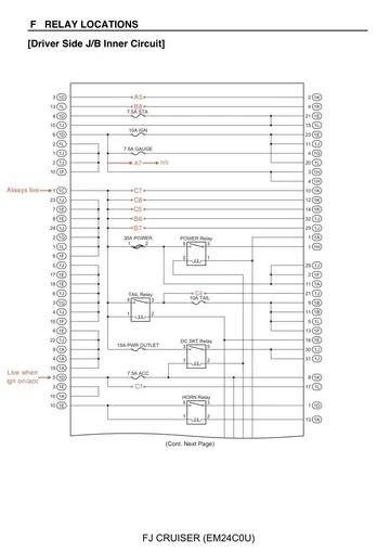
The key to this approach is knowing what connector positions go to which fuse positions. This information is not shown in the FJC electrical wiring diagram (EWD), but it's shown in the images I've included below. Also, you've got several options as there are pre-wired circuits that are always live, ones that are live only when the ignition is on, one that's live in the on or accessory key position, one that's live when the tail lights are on, and two that aren't connected to any power source but available for your needs.

All the details you need to know are shown in the images below or in the accompanying text.

Here's the fuse block I'm talking about showing all the unused positions:
RB3.jpg


Here's a picture from another thread showing how someone used add-a-fuse kits to add their circuits:
AddAFuse.jpg


Here is the page from the EWD showing the fuse positions in column-row format and standard EWD connector designations. For example, the PWR OUTLET fuse is at location B5:
DSJB1.jpg

The back side of the fuse block has relays and more connectors:
DSJB2.jpg


[continued in next post]
 
Last edited:
Here's the circuit diagram from the EWD with the column-row fuse positions added and shows the connector and terminal position within that connector pre-wired to the fuse:
DSJB-Circuits1.jpg

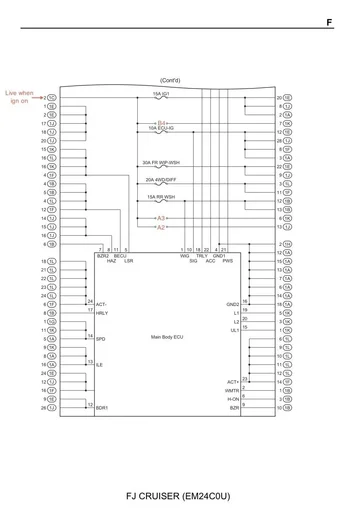
Page 2 of the circuit diagram. I wanted to add a 15A circuit for my seat heaters that was live only if the ignition was on. I chose fuse position A3 for the new circuit and you can see in this photo that it is pre-wired to connector 1K position #6. And then looking at the 4th photo in post #1 above you can see that connector 1K is located on the lower left corner on the rear of the fuse block:
DSJB-Circuits2.jpg
 
Last edited:
So now the work begins. You've got to dissemble the lower DS dash, unbolt the fuse block, and remove connector 1K. I won't go into the details of removing the lower dash, although it is straight forward and documented in the FSM. However since you'll be working on a fuse block that has live circuits in it step 1 is disconnect the battery:
BatteryDisconnected.jpg


Then unbolt the fuse block, unlock connector 1K and remove it:
IMG_1007.jpg


I thought I took photos of removing the black locking bar from 1K and disengaging the terminal retainer but I can't find them now. But the procedure is in the front of the EWD in the "Troubleshooting" section and is pretty easy to figure out. Here's a photo of me disengaging the terminal retainer on a different connector using a dental pick:
IMG_1015.jpg


I crimped my own terminal onto the 16AWG wire I was using. The terminals are available from bmotorsports.com: Home » Shop » Connectors / Harnesses » Sumitomo » Sumitomo TS / SL Female Terminal 0.5 - 1.25 mm2 ( 20 - 16 AWG ). URL: Here http://www.bmotorsports.com/shop/product_info.php/cPath/109_110/products_id/1567 or from another vendor here https://www.theplugdealer.com/shop/product/7534-yazaki-2-3ii-090ii-sealed-connectors-0-5-1-25-mm2-16-22-awg-female-terminal-copper-tin-25248. They were like $12 shipped for quantity 25. But you need a good crimp tool and the proper die. Lacking that just buy a repair terminal from your favorite Toyota dealer:
IMG_1004.jpg


Toyota repair terminal p/n 82998-12340:
IMG_1014.jpg
 
Last edited:
Now insert the terminal into connector 1K at the chosen position (6 is this example). Pay attention to how the terminal positions are numbered. On the fuse block images from the EWD in post #1 there are numbers for the socket in the fuse block and numbers for the connector with all the wires. The image of the connector is looking at the side that interfaces with the socket, while you'll be inserting the terminal from the back side of the connector, so it's like a mirror image. It's easy to do it right, but take your time and double check before you shove the terminal in because it latches and can't just be pulled out without releasing the latch:
IMG_1005.jpg


Here's a photo showing the connector all back together with the new wire in place:
IMG_1006.jpg


After you re-connect the connector to the fuse block you can use a multimeter to verify you got the right fuse position and connector position number. Then just run the wire to wherever it's going and re-assemble the lower dash.

Lastly, be mindful of how much current you'll be drawing with the new circuit. Heavy loads like big light bars should be powered directly from the battery using a relay and dedicated fuse. All of the always-live and all of the switched circuits for this relay block are further protected by 50A fusible links in the engine bay, an indication that Toyota engineers don't expect the total draw of all of these circuits to exceed that number.
 
Last edited:
This post is a placeholder because I plan to add fused circuits to empty places in the engine bay fuse block in the not-too-distant future and will have part numbers and photos of that here. There's already a couple of pre-wired circuits available, one for the offroad light package and one of the auxiliary (aka fog) lights package. These both have relays and wiring sized for 15A circuits. And if your FJC does not have a subwoofer there's a pre-wired always-live 20A circuit available. I'll be using the 20A for a couple outlets in the rear for powering my refrigerator and other accessories.
 
Last edited:
What an excellent, excellent write-up. So you recommend the Paladin crimper? and which dies for most jobs?

I've been very happy with my Paladin PA8000 ratcheting crimper. I've got several die sets: 2033 for non-insulated terminals, 2035 for non-insulated, 2064 for RJ45 connectors, and a die set for Anderson Powerpole terminals that came from another vendor. Their PA1117 wire stripper is also very nice. Shop around for the best deal because prices very a lot.
 
Last edited:
Subscribed as well.
 
This is awesome, thanks.
 
This is an AWESOME guide! I'll be cleaning up all of my add-a-circuits under the dash and under the hood. Thanks again!

-B
 
Thanks for the kudos. Hard to believe it's been three years since I did this. I've still not added any new circuits to empty spots in the engine bay fuse block like I promised in post #5, mainly because there was already an existing circuit meant for off-road lighting and I just tapped into that.
 
Thank you so much for posting this! Ive already maxed out the number of add-a-circuits to my fuse block, which for me was 4. At some point I'll follow your instructions and clean it up and add some more circuits.
 

Users who are viewing this thread

Back
Top Bottom