
So I initially thought there was a general Suspension Tech section of MUD, but there isn't, and so here we are. This is about my Saturday project of rebuilding a coilover shock, instead of sending it across to the west coast to an authorized Icon Vehicle Dynamics rebuilder.
I took on this project for two reasons, 1) to save me the time/$$$ to ship my shocks to a rebuilder, and 2) I wanted to learn something. I watched a couple of youtube instructional videos (I know, right?) and felt this was a challenge I could take up. I was also going to be at ACC, so I knew there would be some help nearby, if I got really stuck. Though they don’t typically do full suspension rebuilds, they had the professional spring compressor and a tank of nitrogen with the needle kit. I also had my old Icon coilovers from many moons ago as a back-up, back-up plan. The most helpful video turned out to be the shortest one. While his application was a different truck, the anatomy of the shock seemed nearly identical. I’m certainly not professing to be any kind of expert on this now, but I wanted to share what I learned.
Note: I also realized I didn’t take pictures at every step. Bear with my lack of pictures on this initial version. I hope to fill that void when I rebuild the passenger side.
After removing the coil spring from the shock body - no easy task if you don’t have a professional spring compressor - the first thing to do is mount the shock in a vise. I also removed the top hat so that I could clamp the shock body in the vise. You’ll need a 13mm 12-sided socket to get the bolt out. Then protect the upper eye of the shock body with a rag or some scrap leather and mount so the shaft is pointed up.
Next I removed the brass gas charging port plug. (I think this is a 13mm, but for me it was very snug. Usually if it’s a ½” bolt head, the 13mm is loose.) Slowly loosen the plug to allow the nitrogen out gradually. Honestly, I was expecting a big woosh, but it was very anti-climactic.
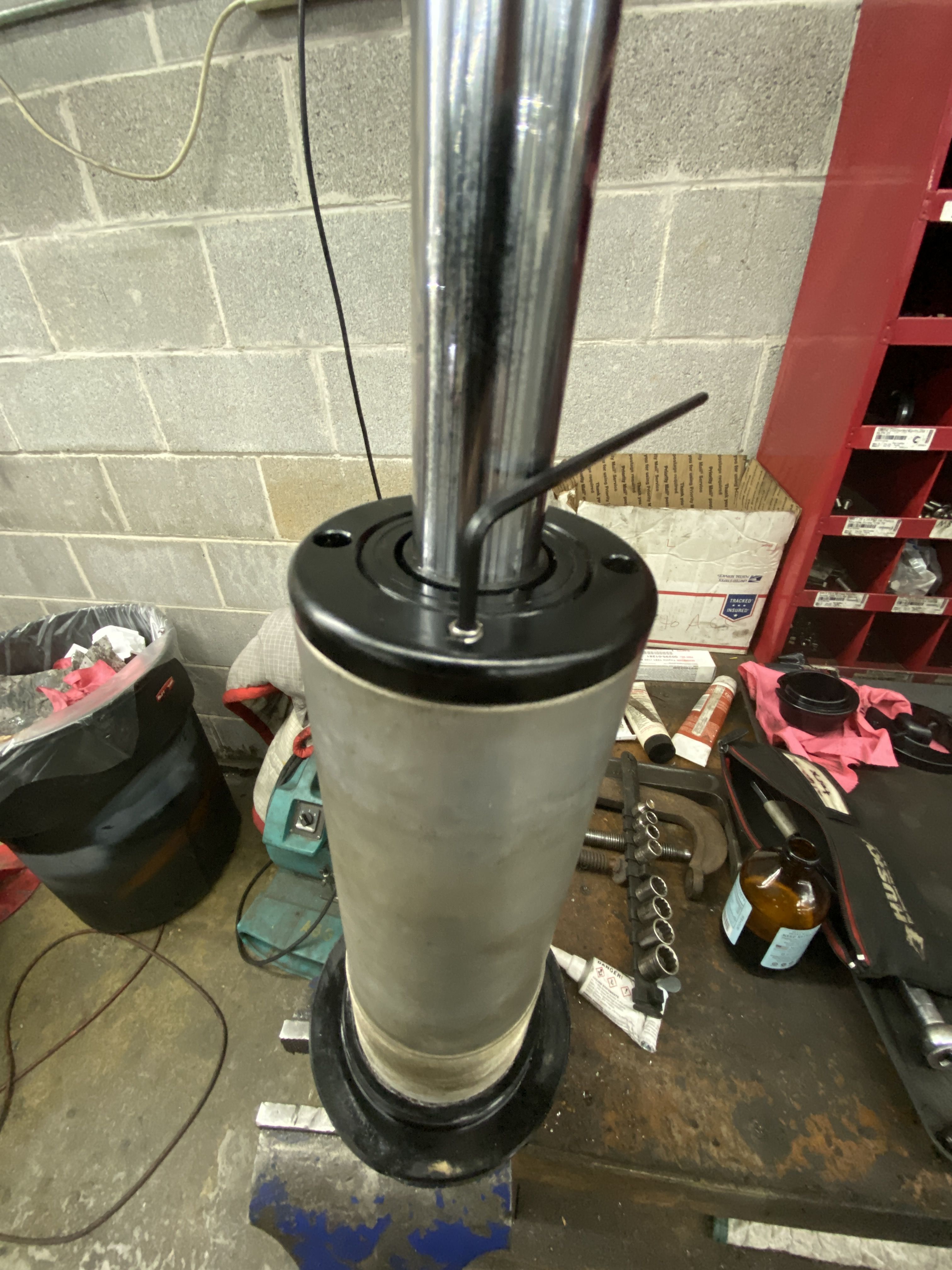
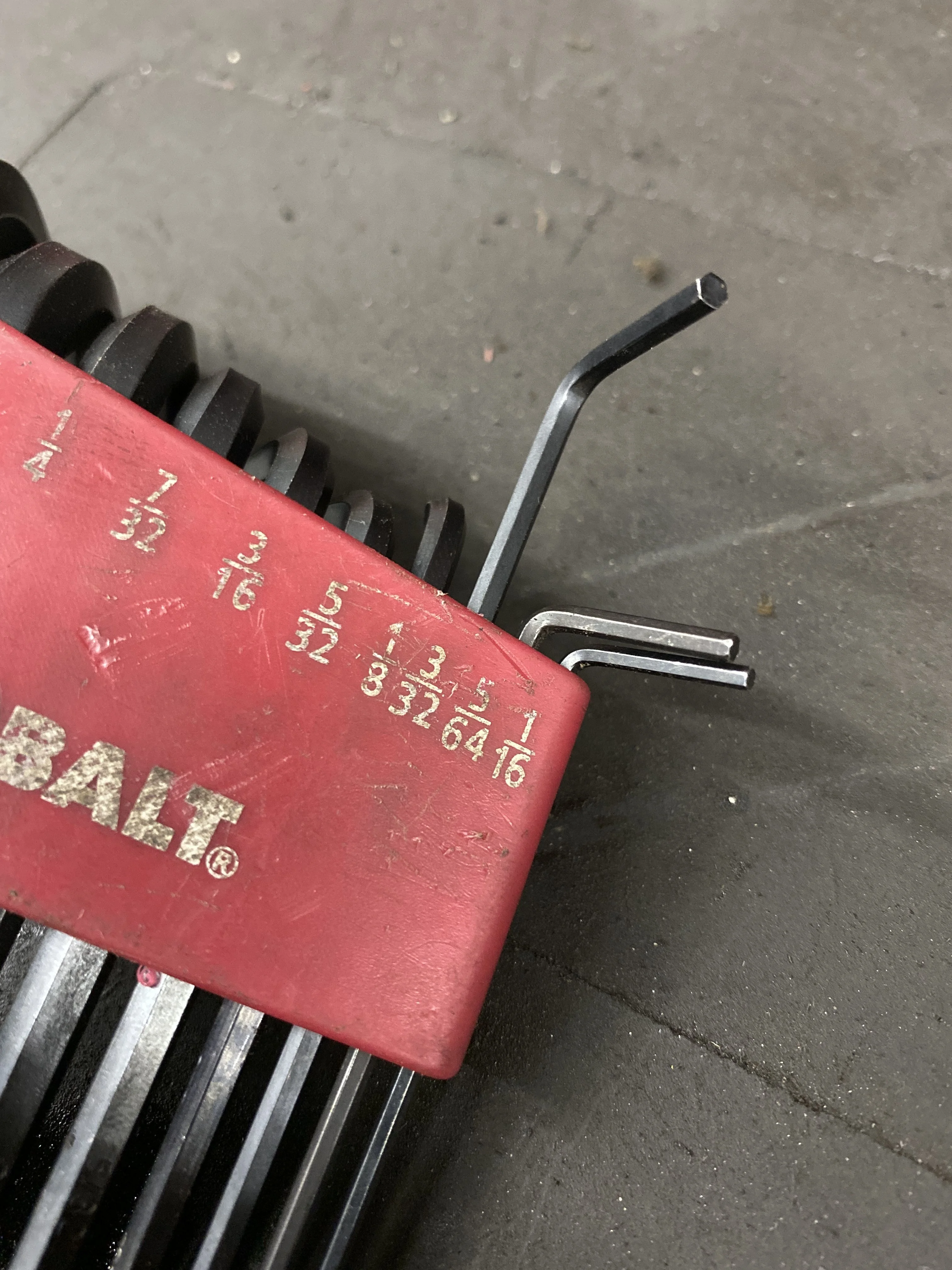
Using a 3/32” allen wrench, loosen the set screw on the lower shock body cap.
Using a spanner wrench with 3/16” pins or a pair of angled needle nose pliers (what I used), unscrew the cap. The threads of the cap engage around the inner shaft of the lower assembly. Once the threaded cap is loose, slide it towards the lower shock mount eyelet and zip tie it out of the way (it won’t come off the end because of the swell at the lower shock mount).
Before the shaft can be completely removed, there is a circ-clip just below the lip of the shock body opening. It pops out super easy, but it is what the screw cap secures against the lower assembly, so there’s no need for it to be super tight in its seat.
Now comes the messy part. Pull the shaft completely free of the shock body. It will take a bit of grunting, but start slowly as it will pull lots of oil with it. The upper part of the piston has a compressed steel sleeve (like an oil ring) and you have to pull hard to get it free of the cylinder wall. If you can position an oil pan under your vise, do it before you start pulling it free. If not, then have plenty of garage towels handy.


Dump the oil in your recycle container and set the shock body aside for now.
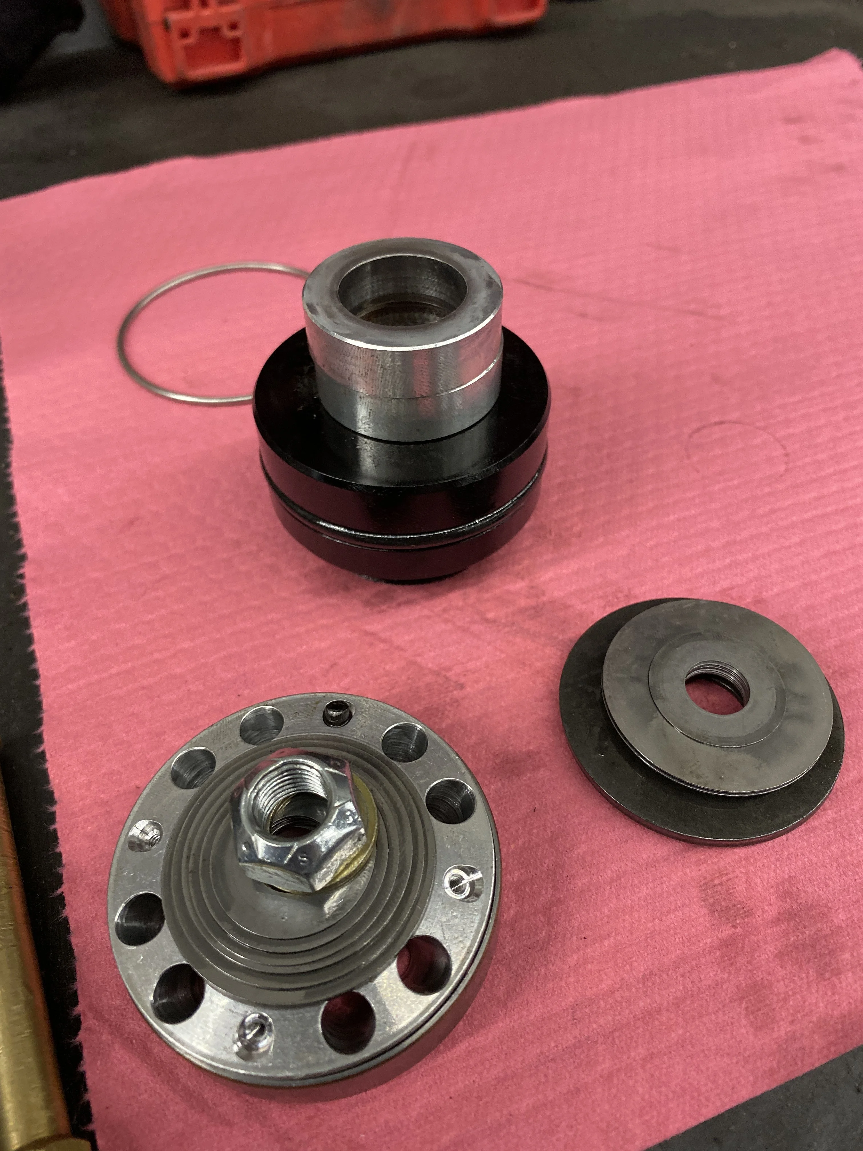
To get the lower assembly off the shaft you need to remove the 17mm nut (again, my socket was very snug), so guessing these are actually SAE sized hardware. This is pretty easy to do, if you have the shaft locked in vise. You don’t want any of these parts flying across the shop. Take your time and set each of these pieces on a clean surface.
This is the cool part. Note the order of the stacks of shims and keep everything in order. There is a stack of about a 9-10 shims in diminishing size on each side of the valve “stack”. The valving in your shocks comes from this stack of shims against the ported puck in bright aluminum here. The shims flex just enough to let the oil pass through at a specific rate of damping. My stack even had one of the four threaded ports plugged with a set screw. I am assuming plugging other ports would affect the valving and each shock is tuned at the factory to specific damping rates.
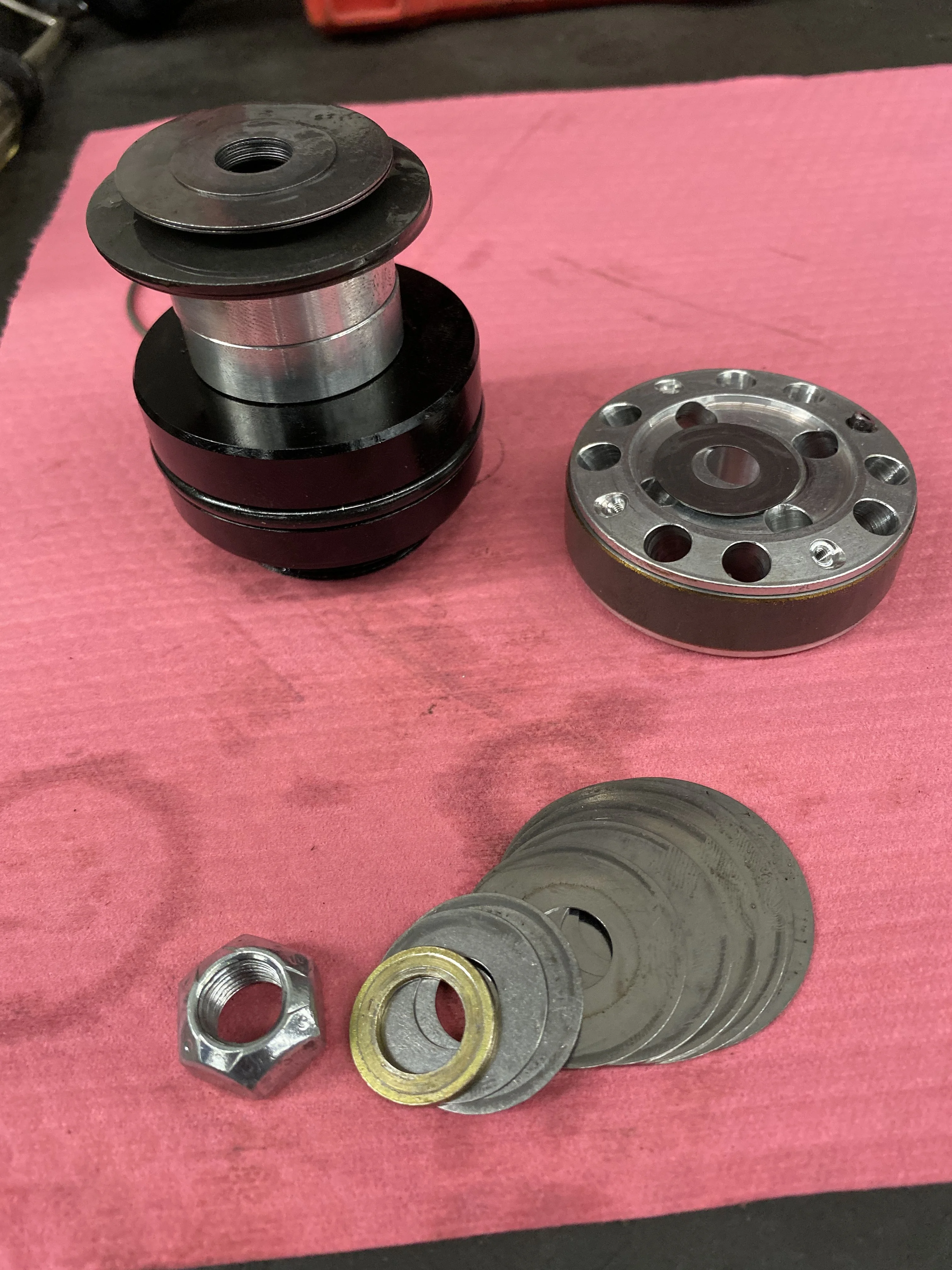
Also on the shaft are two solid ~1/2” aluminum spacers. These have a purpose that is unknown to me, except that they limit the extension of the shock. I imagine they are application specific and keep the valve stack from banging into the lower cap. There is also a larger washer stack that needs to be reused.
The rebuild kit (#252010) I ordered from www.sdhqoffroad.com was $35 and the jug of oil was $65. I don’t have any specifics on the oil, since the jug had no label whatsoever. But it looks suspiciously like ATF. None of this is actually on their website, you'll need to call or email them and tell them what specific model of coilovers or shocks you are trying to rebuild.

The big seals are pretty self-explanatory. They go on the outside of the lower endcap assembly and the upper nitrogen piston (what the guy in the video calls the IFP). OH WAIT, we forgot the nitro piston! It’s still in the shock body. So after poking and prodding with various picks for about 12 fruitless minutes, one of my pals at the shop says, hey just hit the charging port with some air. Genius! I put the gun tip on the air line and *POPPED* the nitro piston out the bottom of the shock body. This piston has a plastic “oil ring” type sleeve, so be careful with it, because it does not get replaced with this rebuild kit.

Now that the big seals are done, the small ones will haunt you. The lower endcap assembly is basically the seal for the exposed shaft and it houses two different seals. The outer black one is the one visible from a full assembled shock. Using a pair of needle nose pliers, just yank that sucker out. It’s flared on the inner side and is a bugger, but it will come out with a good yank.
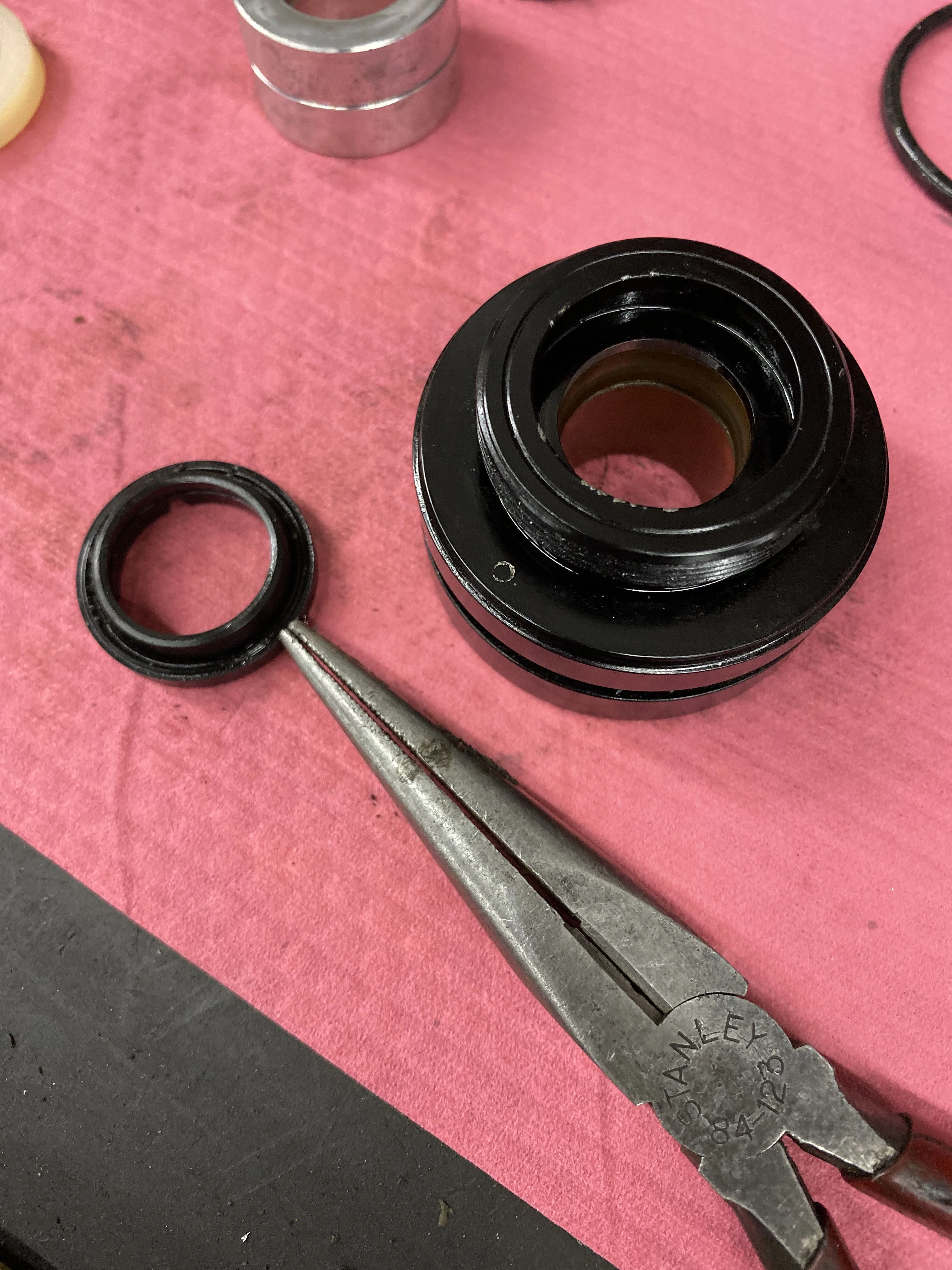
The inner seal is about the same size outer diameter as the black seal and it’s the exact inner diameter size of the hole. There is a Teflon (orange) coated steel sleeve on the other side of this puck, so you don’t want to bugger this up with sharp tools. You starting to see the problem here? The bottom of this white nylon/silicon seal is grooved, so it will catch a hook, if you carefully insert it from the lower edge. Working from the threaded end of the puck (as pictured below) reach into the opening with a hooked pick. Again give it a good yank and it will pop out (and likely fly across the room). Just leave it. You have more important things now. The old seal has turned brown on the edges and you can see the top edge of the Teflon lined steel sleeve below.

So, let me just say a little prayer for you now, because I don’t know how I got the new one in, and you’ll need all the help you can get. I pushed one edge in from the top and it seated, then held it there with a round brass drift. In hindsight, I probably should have used a wooden dowel, but I polished up my brass drifts and proceeded. While holding that one side securely with the 3/8” brass drift, I used a smaller brass drift to push the other edges slowly in around from there. And tried to rotate it all with the larger brass drift to keep it from rolling back out. It took me a good 10-15 minutes of cussing and it popping back out and redoing it all over again before it finally landed in its seat. It seems to have done so unscarred as well. Again using wooden dowels (which I didn’t have on hand), would have been a safer tool to use around the aluminum, Teflon and rubber.

The hard part is over, but now there’s more messiness. Assemble everything back on the shaft and secure the nut on top to 35ft-lbs. Mount the shock body back in your vise and go ahead and put your oil pan back under it.
Place the nitro piston back in the shock body in the correct orientation and use the shaft assembly to seat it down in the tube. Push the piston the length of the shaft. Now put the charging port plug back in the top assembly (10ft-lbs) and replace the small Allen-head fill screw (the kit comes with a new one of each, with an extra charge plug o-ring).
Remove the shaft and set it aside. Now, make sure the shock body is secure in your vise, and fill the tube with oil. You want to fill it practically to the brim. To avoid airspace in the shock body, you’re just going to slowly plunge the shaft assembly into the shock body and let it displace the oil. Start by squeezing the “oil ring” sleeve on the valve stack and slide the piston, keep slowly plunging.
At some point you will hit some resistance and won’t get the endcap to seat. What I recommend is to hold the endcap against the top of the shock body as closely as you can and pull the shaft out through the endcap. This will allow more displacement to plunge the endcap further until it clears the top lip of the shock body. You will need to seat it just enough to pop the circ-clip back in. You can see how much oil I used from the jug there.
Now you can slip the threaded seal cap back down the shaft (if you zip-tied it earlier) and start to thread it onto the endcap. Using your spanner wrench or angled needle nose, give it a good 1-ugga on the elbow-o-meter torqueness. I honestly don’t know the torque spec on this endcap, but it’s aluminum on aluminum and I didn’t want to overcrank it and funk up the project. Reinsert the set screw to lock it in place.
Now, all that’s left is reassembly of the top plate and spring. The last step is nitro charging of the assembly. I chose to start with 150psi and I probably over-estimated that number. From the driver seat, it appears to be a bit tight compared to the passenger side, but then my passenger side probably needs to be rebuilt and recharged as well. The passenger side is not leaking like the driver side was, so it’s on my list, but not emergent.
I took on this project for two reasons, 1) to save me the time/$$$ to ship my shocks to a rebuilder, and 2) I wanted to learn something. I watched a couple of youtube instructional videos (I know, right?) and felt this was a challenge I could take up. I was also going to be at ACC, so I knew there would be some help nearby, if I got really stuck. Though they don’t typically do full suspension rebuilds, they had the professional spring compressor and a tank of nitrogen with the needle kit. I also had my old Icon coilovers from many moons ago as a back-up, back-up plan. The most helpful video turned out to be the shortest one. While his application was a different truck, the anatomy of the shock seemed nearly identical. I’m certainly not professing to be any kind of expert on this now, but I wanted to share what I learned.
Note: I also realized I didn’t take pictures at every step. Bear with my lack of pictures on this initial version. I hope to fill that void when I rebuild the passenger side.
After removing the coil spring from the shock body - no easy task if you don’t have a professional spring compressor - the first thing to do is mount the shock in a vise. I also removed the top hat so that I could clamp the shock body in the vise. You’ll need a 13mm 12-sided socket to get the bolt out. Then protect the upper eye of the shock body with a rag or some scrap leather and mount so the shaft is pointed up.
Next I removed the brass gas charging port plug. (I think this is a 13mm, but for me it was very snug. Usually if it’s a ½” bolt head, the 13mm is loose.) Slowly loosen the plug to allow the nitrogen out gradually. Honestly, I was expecting a big woosh, but it was very anti-climactic.
Using a 3/32” allen wrench, loosen the set screw on the lower shock body cap.
Using a spanner wrench with 3/16” pins or a pair of angled needle nose pliers (what I used), unscrew the cap. The threads of the cap engage around the inner shaft of the lower assembly. Once the threaded cap is loose, slide it towards the lower shock mount eyelet and zip tie it out of the way (it won’t come off the end because of the swell at the lower shock mount).
Before the shaft can be completely removed, there is a circ-clip just below the lip of the shock body opening. It pops out super easy, but it is what the screw cap secures against the lower assembly, so there’s no need for it to be super tight in its seat.
Now comes the messy part. Pull the shaft completely free of the shock body. It will take a bit of grunting, but start slowly as it will pull lots of oil with it. The upper part of the piston has a compressed steel sleeve (like an oil ring) and you have to pull hard to get it free of the cylinder wall. If you can position an oil pan under your vise, do it before you start pulling it free. If not, then have plenty of garage towels handy.
Dump the oil in your recycle container and set the shock body aside for now.
To get the lower assembly off the shaft you need to remove the 17mm nut (again, my socket was very snug), so guessing these are actually SAE sized hardware. This is pretty easy to do, if you have the shaft locked in vise. You don’t want any of these parts flying across the shop. Take your time and set each of these pieces on a clean surface.
This is the cool part. Note the order of the stacks of shims and keep everything in order. There is a stack of about a 9-10 shims in diminishing size on each side of the valve “stack”. The valving in your shocks comes from this stack of shims against the ported puck in bright aluminum here. The shims flex just enough to let the oil pass through at a specific rate of damping. My stack even had one of the four threaded ports plugged with a set screw. I am assuming plugging other ports would affect the valving and each shock is tuned at the factory to specific damping rates.
Also on the shaft are two solid ~1/2” aluminum spacers. These have a purpose that is unknown to me, except that they limit the extension of the shock. I imagine they are application specific and keep the valve stack from banging into the lower cap. There is also a larger washer stack that needs to be reused.
The rebuild kit (#252010) I ordered from www.sdhqoffroad.com was $35 and the jug of oil was $65. I don’t have any specifics on the oil, since the jug had no label whatsoever. But it looks suspiciously like ATF. None of this is actually on their website, you'll need to call or email them and tell them what specific model of coilovers or shocks you are trying to rebuild.
The big seals are pretty self-explanatory. They go on the outside of the lower endcap assembly and the upper nitrogen piston (what the guy in the video calls the IFP). OH WAIT, we forgot the nitro piston! It’s still in the shock body. So after poking and prodding with various picks for about 12 fruitless minutes, one of my pals at the shop says, hey just hit the charging port with some air. Genius! I put the gun tip on the air line and *POPPED* the nitro piston out the bottom of the shock body. This piston has a plastic “oil ring” type sleeve, so be careful with it, because it does not get replaced with this rebuild kit.
Now that the big seals are done, the small ones will haunt you. The lower endcap assembly is basically the seal for the exposed shaft and it houses two different seals. The outer black one is the one visible from a full assembled shock. Using a pair of needle nose pliers, just yank that sucker out. It’s flared on the inner side and is a bugger, but it will come out with a good yank.
The inner seal is about the same size outer diameter as the black seal and it’s the exact inner diameter size of the hole. There is a Teflon (orange) coated steel sleeve on the other side of this puck, so you don’t want to bugger this up with sharp tools. You starting to see the problem here? The bottom of this white nylon/silicon seal is grooved, so it will catch a hook, if you carefully insert it from the lower edge. Working from the threaded end of the puck (as pictured below) reach into the opening with a hooked pick. Again give it a good yank and it will pop out (and likely fly across the room). Just leave it. You have more important things now. The old seal has turned brown on the edges and you can see the top edge of the Teflon lined steel sleeve below.
So, let me just say a little prayer for you now, because I don’t know how I got the new one in, and you’ll need all the help you can get. I pushed one edge in from the top and it seated, then held it there with a round brass drift. In hindsight, I probably should have used a wooden dowel, but I polished up my brass drifts and proceeded. While holding that one side securely with the 3/8” brass drift, I used a smaller brass drift to push the other edges slowly in around from there. And tried to rotate it all with the larger brass drift to keep it from rolling back out. It took me a good 10-15 minutes of cussing and it popping back out and redoing it all over again before it finally landed in its seat. It seems to have done so unscarred as well. Again using wooden dowels (which I didn’t have on hand), would have been a safer tool to use around the aluminum, Teflon and rubber.
The hard part is over, but now there’s more messiness. Assemble everything back on the shaft and secure the nut on top to 35ft-lbs. Mount the shock body back in your vise and go ahead and put your oil pan back under it.
Place the nitro piston back in the shock body in the correct orientation and use the shaft assembly to seat it down in the tube. Push the piston the length of the shaft. Now put the charging port plug back in the top assembly (10ft-lbs) and replace the small Allen-head fill screw (the kit comes with a new one of each, with an extra charge plug o-ring).
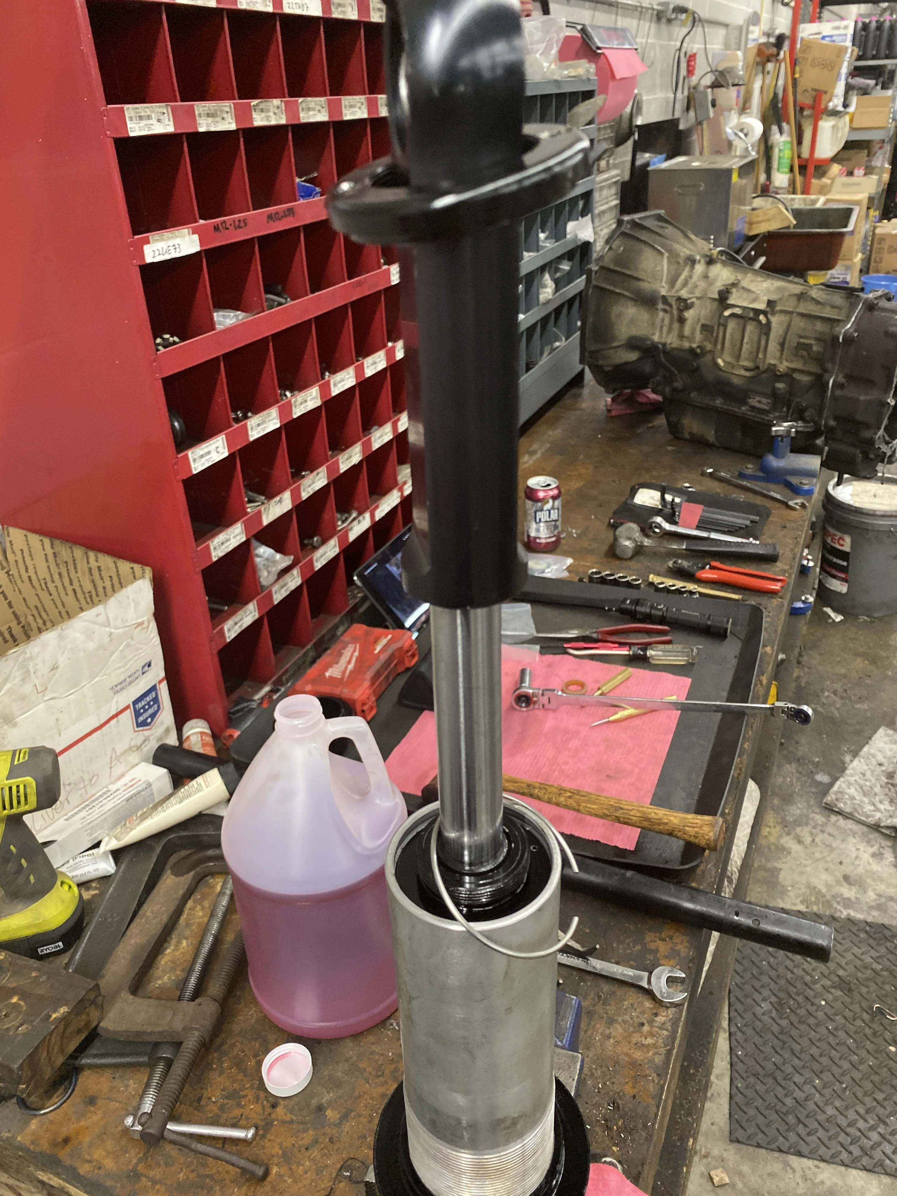
Remove the shaft and set it aside. Now, make sure the shock body is secure in your vise, and fill the tube with oil. You want to fill it practically to the brim. To avoid airspace in the shock body, you’re just going to slowly plunge the shaft assembly into the shock body and let it displace the oil. Start by squeezing the “oil ring” sleeve on the valve stack and slide the piston, keep slowly plunging.
At some point you will hit some resistance and won’t get the endcap to seat. What I recommend is to hold the endcap against the top of the shock body as closely as you can and pull the shaft out through the endcap. This will allow more displacement to plunge the endcap further until it clears the top lip of the shock body. You will need to seat it just enough to pop the circ-clip back in. You can see how much oil I used from the jug there.
Now you can slip the threaded seal cap back down the shaft (if you zip-tied it earlier) and start to thread it onto the endcap. Using your spanner wrench or angled needle nose, give it a good 1-ugga on the elbow-o-meter torqueness. I honestly don’t know the torque spec on this endcap, but it’s aluminum on aluminum and I didn’t want to overcrank it and funk up the project. Reinsert the set screw to lock it in place.
Now, all that’s left is reassembly of the top plate and spring. The last step is nitro charging of the assembly. I chose to start with 150psi and I probably over-estimated that number. From the driver seat, it appears to be a bit tight compared to the passenger side, but then my passenger side probably needs to be rebuilt and recharged as well. The passenger side is not leaking like the driver side was, so it’s on my list, but not emergent.