Generic Aftermarket Glow Plug Pre-Heating Timer

This site may earn a commission from merchant affiliate
links, including eBay, Amazon, Skimlinks, and others.

Jonathan_Ferguson

★ is in the wrong locale
Joined
Jul 2, 2003
Threads
132
Messages
950
Location
Glen Waverley, Victoria, Australia
Website
jonathan-ferguson.au
I've been stumbling about for a while now.
https://forum.ih8mud.com/79-95-toyo...gulator-brake-mastercylinder.html#post8761665

I'm at the stage where I need to perform tests by bridging from a hot conductor in the 10 position connector to the conductor which illuminates the dash light and to the conductor that is the signal wire to the relay.

I have opened the original Pre-Heating Timer and I couldn't find any visual identifiers of a problem. - I did start reverse engineering the circuitboard in Fritzing but I gave-up after I couldn't find-out three of the four types of transistors from their numbers, also one of the diodes is mounted in way that I can't see it's entire number.
I don't want to start disassembling the board until after I've confirmed that the dash light illuminates and that the wire to the bus bar is getting juice.

I have commenced researching glow plug timers, thus far I've found only three products from Bogaard 1 2 3 and this thing on ebay.
The Bogaard DGT1 won't work because my Hilux doesn't have after glow. The GT10 is just a push button, and the DGT2 [along with the others] do not take into account for the resistance of the Temperature Sensor.
Another thing that makes these timers unacceptable to me is that none state that they include a Nippon Denso 10 position male connecter which can have their conductors pushed into.

What can I do which emulates OEM as close as possible?
 
I did make a "Monostable Multivibrator" using a 555 Timer integrated circuit but it wouldn't turn off. - I can only guess why, that the IC is rated to a maximum of 200mA but my circuit was sinking 674mA.

I have a acquired a Pre-Heating Timer 28521-54560 supersedes 28521-54450 for a LN67R-MDN. It has the same pin assignments as my original except for not having an engine temperature circuit. I do not know what Toyota did with LN67 to gauge glow duration, but my guess is that the Water Temperature Sensor would be connected in series to the Timer's Ignition pin. - Because current leads voltage, the capacitors inside of the Pre-Heating Timer would take longer to charge when the thermistor(Water Temperature Sensor) has greater resistance resulting in a longer glow time when the engine is cooler.

Any ideas on sources for a connector which can be inserted into the Fujitsu Ten on the left, and a wire-able connector that is the same as the Nippon Denso on the right?

attachment.php

Fujitsu Ten on left; Nippon Denso on right


Currently I have to use a paperclip between pins 1 and 3

attachment.php

MacGyver method


To go sans Glow Plug Timer I would still need to source a connector to attach to the loom and a Double Pole Single Throw momentary switch that is 1" high and 42 ~ 44mm wide, any ideas from where I can get one?
One side of the switch when pushed would conduct the circuit between pins 7 [Ground] and 8 [Glow Indicator Light], whilst the other circuit would conduct the circuit between pins 1 [Glow Plug Relay] and 3 [Ignition].

attachment.php

This is the sole blank receptacle.
 
Last edited:
Hi Jonathan,

So we're talking about a 1985 HiLux (LN65R) Aussie, RHD, 5 speed? Right?
The first question is; pre or after July 1985. There are a few differences in that glow circuit when I look at the EPC.
From what I read and see in the EPC it looks like you have a "Super Glow" system but you wrote that you don't have afterglow?? Are you sure about that?
I don't have the FSM for a 2L engine but I do have a FSM for the 2L-T/3L engines (1995 and later) and those engines do have after glow.

So next question is... do you have the correct diagram for your 2L engine so we can see what we're dealing with and can you post it here?

That glow timer is surrounded by fusible links and a bunch of components which can easily lead to malfunctioning of that timer.

Rudi
 
Thanks for investing your time with this.

My Hilux is a June 1985 without Super Glow. I have written a lot of information about what has happened.
The teacher I mentioned, ended up being a regular teacher of myself so I had him go over all of the components. By this stage I had identified all of the components except for two, the three terminal NEC product which ended up being a PNP transistor which I labeled as B C E and a Single Inline package with "T T2563 5C". At this point all components checked out except that the T2563 remains unidentifiable.

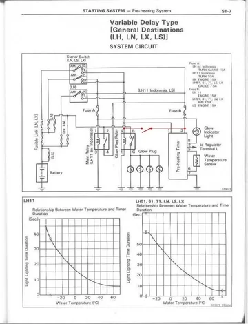
Theses diagrams are an exact depiction of my setup.
http://htmlimg1.scribdassets.com/28useg3qyo5gcw5/images/149-7aa6e9a0cc/000.jpg
http://htmlimg3.scribdassets.com/28useg3qyo5gcw5/images/150-e56421a648/000.jpg

Regarding the Monostable Multivibrator, I can simulate what should occur but reality is different. I tried with and then without the Voltage Divider framework.
http://www.falstad.com/circuit/#$+1...0+0+5500.0 o+5+64+0+34+20.0+9.765625E-5+0+-1
The 330Ω resistor signifies the Water Temperature Sensor when hot.
The 6V supply attached to the Reset pin signifies the Regulator's Terminal L, which will extinguish the 555 Timer when it exceeds 2/3 of Vin. - This is when the engine is rotating, the Glow Plugs will be turned off.
In addition to the above, a relay would need to be wired as an inverter gate signaled by the Output pin of the 555 Timer to drive the Glow Indicator Light.

• If I could find compatible connectors and I wired the Fujitsu Ten as per the labels on the PCB, I expect it would act as constant delay in my Hilux.
• If I could find a connector to attach to my loom and an appropriately sized switch; I could activate the Glow Plugs manually along with the Glow Indicator Light.
 
Hi Jonathan,

Let's see where to begin.....
You have a "Variable Delay" glow system which is basically a "Super Glow" without the after glow function.
I assume that you have checked all the required voltages, checked all the connections for bad contacts and corrosion and that all the fuses and fusible links are OK. In other words.... the problem is not in the components that are attached to the Pre Heating Timer.

I think that your Transistor is the 2N2563-5. A PNP power transistor. Here are the specs. http://alltransistors.com/transistor.php?transistor=2151
Or it's a 2SC2563 NPN power transistor with these specs: http://www.alldatasheet.com/datasheet-pdf/pdf/268721/ISC/2SC2563.html

I'm not going into the mono flip flop that you've build. It's too long ago that I was building my own circuits.

If you want to switch to "manual glow" aka "Wilson Switch" that's pretty simple.
All you need is a momentary switch. You already have 11V glow plugs so there is no problem on the plugs.
BTW, in your other thread you said that all the glow plugs....

All of the glow plugs are shorted and all have less than 20 Ω of resistance.

I may hope that there is a typo in that quote. All plugs should be around 1Ω or less than 2Ω.

Here is the diagram. Just ad hook up the momentary switch between "g" on the glow relay and pin3 on the pre heating timer.
Variable Delay (Hi Lux) Wilson Switch.jpg
If you want you can hook up a control light to the bus bar Bus bar (or G terminal on the Glow Relay) to ground.

Rudi

Variable Delay (Hi Lux) Wilson Switch.jpg
 
Last edited:

Users who are viewing this thread

Back
Top Bottom