Where does the red SOLENOID POWER wire connect to? Using EZ Harness

This site may earn a commission from merchant affiliate
links, including eBay, Amazon, Skimlinks, and others.

everything, after you get it all working i would heat shrink and solder all connectors, that way they wont oxodize or brake apart as easily.
 
reading though posts here, but havnt seen anywhere that the starter has engaged. does it work?
 
Last edited:
If you replace the wire, you have to use the same size or larger wire.

Jumping across the terminals is just a test. You don't want to have to get our of your truck every time you want to start it. It is also an easy way to turn the engine over when you are working on it. It might take 15 seconds to do it. Just use a screw driver.
 
If you replace the wire, you have to use the same size or larger wire.

Jumping across the terminals is just a test. You don't want to have to get our of your truck every time you want to start it. It is also an easy way to turn the engine over when you are working on it. It might take 15 seconds to do it. Just use a screw driver.

Ok, good to know.

Right, sorry, I was having a difficult time picturing what all that test would entail. I'm pretty sure I understand what you're saying now though. I'll have to try that next time I have a chance to work on it.

I appreciate all of your help and for putting up with my lack of knowledge! ;)
 
reading though posts here, but havnt seen anywhere that the starter has engaged. does it work?

That'd be correct. Starter has not made a sound the whole time, so I'm pretty sure I'm missing something, such as what pin head and I have been discussing about the power to the chassis and ign sw via that white wire...

I'll have to post more pics this weekend, maybe tomorrow if I get a chance.
 
Update:

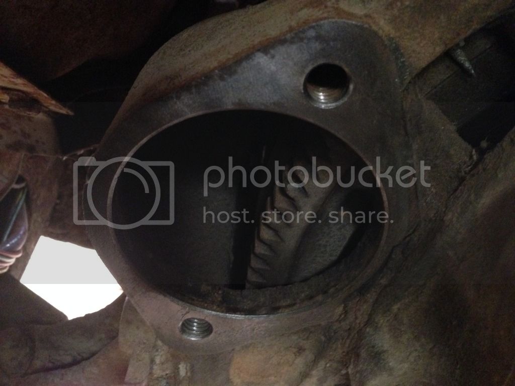
Cleaned up the metal where my starter and (-) batt cable make contact so this is what they look like now...also sprayed some contact cleaner on there just for grins.

This was super rusty so this should help, although I'm not sure if it will solve my problem, just cleaning things up.

IMG_5369_zpswppeuoty.jpg


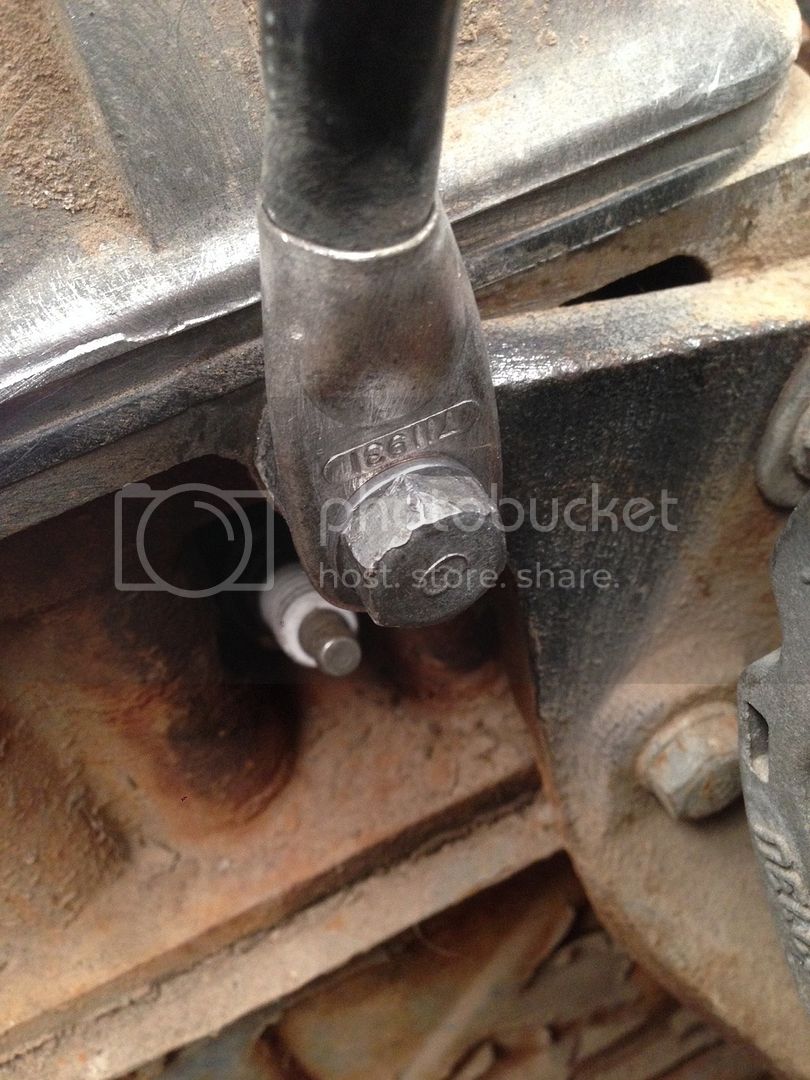
Then there's the (-) batt cable contact. You can tell the difference from what I've cleaned and the spots I couldn't reach.

IMG_5370_zpsm6sxsdch.jpg


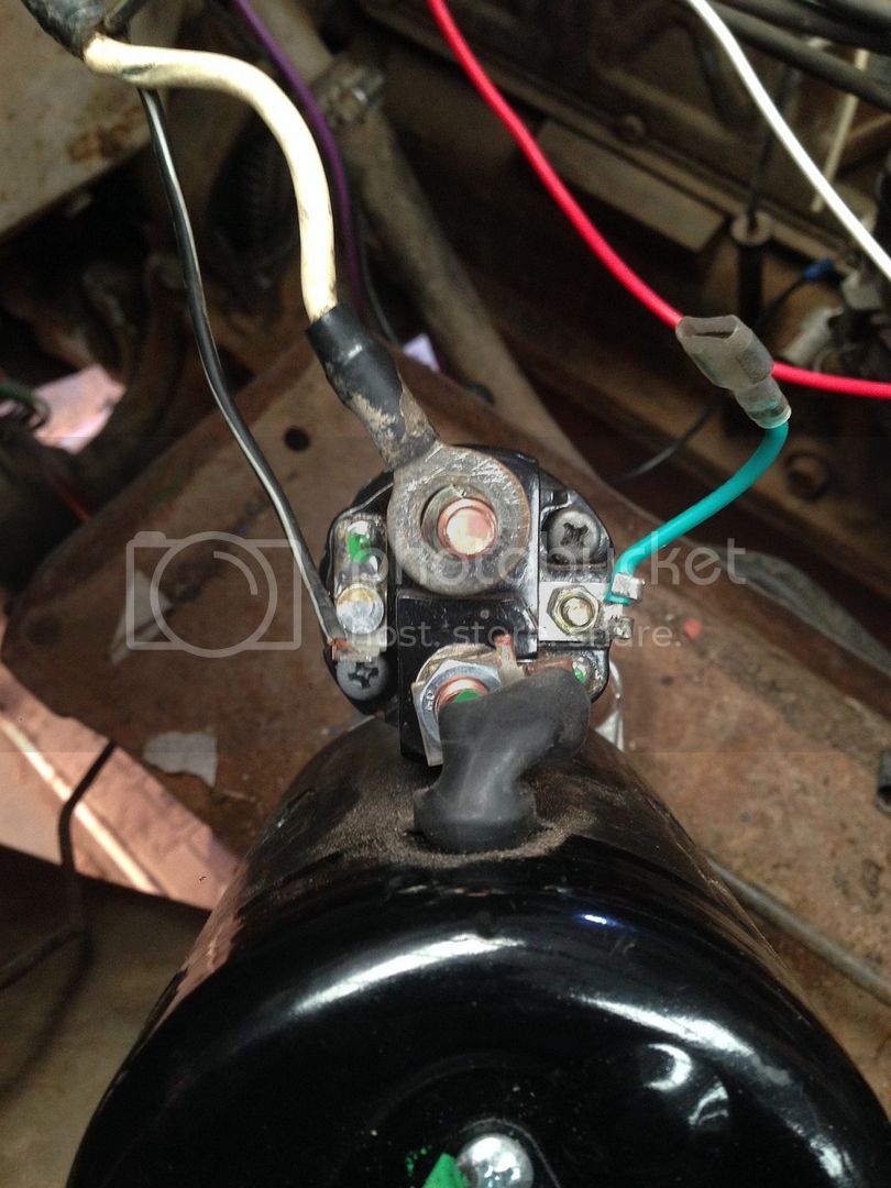
Now, for the more important thing that Pin_Head pointed out, this ampmeter wire. It's the white wire that connects to the center post of the starter solenoid.

IMG_5372_zpsnx9j4yfb.jpg


This wire might be good, not really sure. Anyway, it makes contact with the (+) batt cable on the center post of the solenoid. The way it was originally was that black and white wire was the ign start wire and the white wire was the ampmeter wire. The only other thing wired up to the solenoid was the (+) batt cable.

So, I've got the new ign start wire on the spade lug, and the (+) batt cable, but I haven't tried it with the white wire.

What pin head pointed out is that I'm not getting juice to my ign switch or my chassis

X2

I don't see any connection from the chassis and ignition switch to the battery.

No juicy, no worky.

The OEM power feed for the chassis goes from the battery + post through the fusible link via a large white wire that goes to the amp meter. There it joins power coming in from the alternator and then goes to the ignition switch where it splits into two main branches. One goes directly to the fuse block to provide unswitched power that is always hot. The other branch goes through the switch to provide power to fuse block for things like the tun signals that are only hot when the key is on. There are two main buss bars in the fuse block: One with constant power and one that has power only when the key is on.

HTH

Also drew some revelational-to-me conclusions as noted in the quote above.

So, the update is I'm in the process of hunting these wires down and trying to reconfigure everything to my new fuse block.

Here are the diagrams I have been using:
Screenshot%202015-12-20%20at%206.24.26%20PM_zps44aaynw2.png

Screenshot%202015-12-20%20at%206.24.49%20PM_zpsswt8c4kh.png


So, assuming pin head is right, I just need to find where all of these wires come in to play here on the diagram and try to duplicate that.

I'm pretty sure that I've got the first part, the white ampmeter connects to the (+) batt cable at the solenoid. Now I just need to figure out where "It joins power coming in from the alternator and then goes to the ignition switch where it splits into the two main branches. One goes directly to the fuse block to provide unswitched power that is always hot. The other branch goes through the switch to provide power to fuse block for things like the tun signals that are only hot when the key is on."

So that's what I'll be doing this week, I will let you know what I find out!

Thanks again for all of your help gentlemen!
 
It is pretty obvious where everything goes when you get your head under the dash and look for wires of the proper size and color code. One clue is that the power feed wires are larger than the rest.

The power comes from the battery via the white wire, which connects to the + lug of the amp meter.
All the power goes through the meter.
The power wire (white/blue) from the alternator joins the - lug of the amp meter.
Another wire runs from the - lug of the amp meter to the power post of the ignition switch.
Another wire connects to the power input of the ignition switch and supplies the constant power buss bar of the fuse block.
The Ign position of the ignition switch provides power to the coil and to the key on buss bar of the fuse block.
The start position of the ignition switch goes to the starter solenoid.

That is all you need to run the truck and provide power to the EZ fuse block.
HTH
 
It is pretty obvious where everything goes when you get your head under the dash and look for wires of the proper size and color code. One clue is that the power feed wires are larger than the rest.

The power comes from the battery via the white wire, which connects to the + lug of the amp meter.
All the power goes through the meter.
The power wire (white/blue) from the alternator joins the - lug of the amp meter.
Another wire runs from the - lug of the amp meter to the power post of the ignition switch.
Another wire connects to the power input of the ignition switch and supplies the constant power buss bar of the fuse block.
The Ign position of the ignition switch provides power to the coil and to the key on buss bar of the fuse block.
The start position of the ignition switch goes to the starter solenoid.

That is all you need to run the truck and provide power to the EZ fuse block.
HTH

You are the man! Thank you so much for this! You are really helping me clear things up.

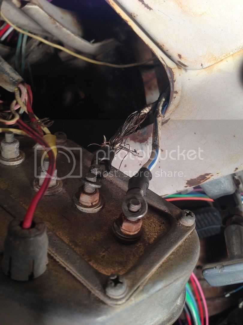
I traced that white wire back and sure enough it does run to the ampmeter as you said. (didn't doubt you btw lol)

That is where I found that blue/white wire that runs to the alternator as well.

Here's a pic: (My instrument cluster is pretty much worthless as far as I can tell too so I hope that doesn't effect the whole circuit...?)
IMG_5379_zpsipskc1lf.jpg


I threw them on the wrong sides in this picture because they were unattached when I found them and I didn't know where they went before you told me.

That white wire looks pretty useless now, totally melted and frazzled as you can see.

Ok, so now I need to rewire the white wire and then get that new alternator wire to the ampmeter as well. The only problem is, my new EZ alternator power wire only seems to run from the fuse block and directly to my alternator. I didn't have enough time to cut through the old harness and see how they had originally wired that blue/white wire, but it seems like it is going to three different places:

1. The alternator
2. The ampmeter
and 3. The fuse block?

I didn't actually see the right sized blue/white wire attached to the old fuse block, but I did see a smaller gauge blue/white wire attached...I'm thinking I just need to trace it back to the harness and see if it is connected to the old, larger blue/white alternator power wire.

So that leads me to wondering if the original wiring of the blue/white alternator power wire only goes from the ampmeter and directly to the alternator..?

If so, that might be a small (solvable) problem seeing that my EZ alternator power wire seems to only go from the fuse block and directly to the alternator, and completely bypasses the ampmeter...so how do I go about solving that?

Should I just splice the new alternator power wire so that it goes from the fuse block, alternator, and ampmeter?

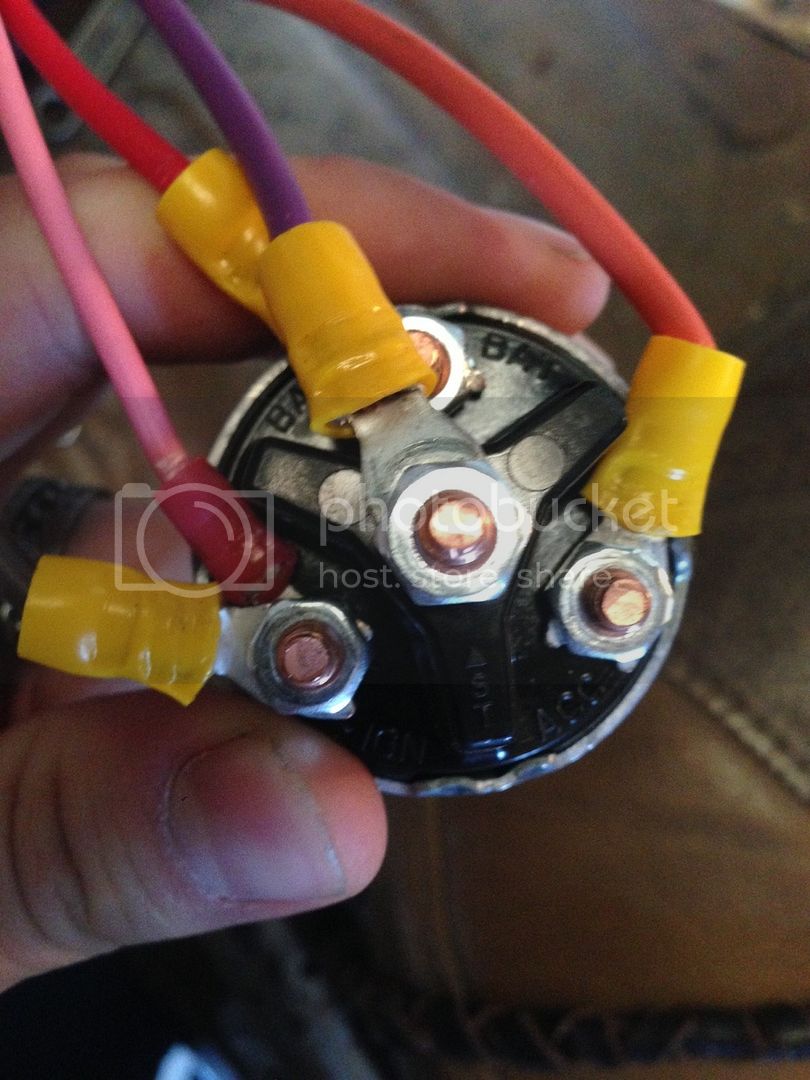
And one more dumb question for now...which one of these posts on the ign sw are you referring to as the "power post"
IMG_5363_zps2cimbswi.jpg


Is it the center post ST, or is it IGN, ACC, or BAT?

Oh, I almost forgot, when you say "Another wire connects to the power input of the ignition switch and supplies the constant power buss bar of the fuse block."

Do any of these wires I already have wired up happen to be that wire?

I can't thank you enough for all of the insightful information you are providing! I am so stoked to see if this will do the trick to get the truck to crank over.
 
The post labeled BAT (for battery) is the power input to the switch. IGN has the wires to the coil and to the switched side of the fuse block. The ST wire goes to the starter solenoid and ACC is for accessories part of the fuse block.

The alternator wire could connect at the fuse block, ignition switch or the amp meter. All these are connected together on the same line, so it doesn't really matter where they are physically connected because they are all electrically the same.

You need to replace the white wire from the battery to the amp meter and any other burned wire that you might need in the harness.

The EZ fuse block has to have a wire that connects to the battery somewhere for unswitched power. This should go to the ignition switch, then to the amp meter and then the battery. All power in and out of the battery goes through the amp meter or it won't work properly.
 
The post labeled BAT (for battery) is the power input to the switch. IGN has the wires to the coil and to the switched side of the fuse block. The ST wire goes to the starter solenoid and ACC is for accessories part of the fuse block.

The alternator wire could connect at the fuse block, ignition switch or the amp meter. All these are connected together on the same line, so it doesn't really matter where they are physically connected because they are all electrically the same.

You need to replace the white wire from the battery to the amp meter and any other burned wire that you might need in the harness.

The EZ fuse block has to have a wire that connects to the battery somewhere for unswitched power. This should go to the ignition switch, then to the amp meter and then the battery. All power in and out of the battery goes through the amp meter or it won't work properly.

Hey, I'm back at it again.

I found something that I think illustrates what you are talking about,
Screenshot%202016-01-13%20at%205.41.34%20PM_zpsgqj3djrf.png


By what you have described, it sounds like you are referring to the diagram on the top left, am I right?

I'm thinking I should follow this, it came out of a seemingly legitimate Toyota Motor Corp. Body and Chassis Repair manual free pdf I downloaded from cardiagn.com

Also, in my case, is my white amp meter wire acting as the fusible link in this daigram?
 
Yes, it is like Figure 8-1, except the circuit shown lacks a ballast resistor and the bypass wire from the starter. You need the resistor because you have a ballast resistor type coil, so it goes in series with the ignition wire at the + side of the coil. The resistor is not polarized, so you can connect either end to the wire and the other to the coil +.

The white wire that provides all the chassis power does not have a fusible link. Early cruisers (before 74 approx.?) lacked them. They are a good idea, so you might consider adding a short piece of fusible link to the white wire at the starter motor.
 
FullSizeRender%2014_zpsbwvghqrm.jpg


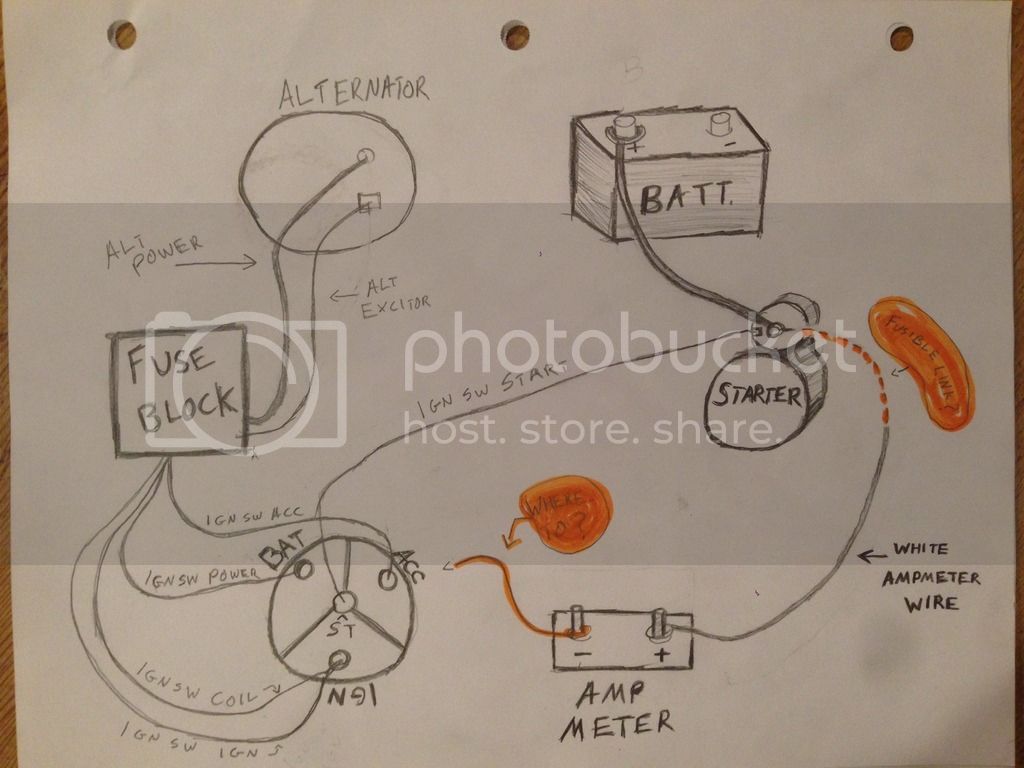
****(Keep in mind that this is how my alternator is wired with the EZ harness. I know the FJ diagrams say to wire the alt power wire to the - of the amp meter, but in my case, it runs back to the fuse block.)****


Here's how I am understanding things need to be wired so far...

I have a few main questions though;

1. where exactly should I use the fusible link?

As you should be able to see, to the right side of the sketch, there is the starter and the fusible link which I have highlighted orange. If I am understanding you correctly, I should run maybe a 6 inch long or so piece of the fusible link wire which came with my harness, from the solenoid, and connect it to the white amp meter wire...correct?

2. secondly, where do I connect this said wire from the - of the amp meter to the ignition sw? (I've also highlighted this orange)

I'm referring to your earlier quote when you said,

"Another wire runs from the - lug of the amp meter to the power post of the ignition switch."

I'm still uncertain of what the "power post of the ign sw" is. Is it the ST, the BAT, the IGN, or the ACC posts?

3. what gauge should the wire from the - of the amp meter be?

The same as the white amp meter wire?

4. Which wire are you referring to when you say, (I am also referring to an earlier quote here)

"Another wire connects to the power input of the ignition switch and supplies the constant power buss bar of the fuse block." ???

Is it one of the wires I already have coming off of my ign sw? Because as far as I can tell, my IGN SW power,
IGN SW ACC, IGN SW COIL, and IGN SW IGN wires all run right back to the fuse block already....so are you referring to some other wire? Or are one of these wires doing the job to supply the constant power to the buss bar of the fuse block already?


I realize that I don't have the ballast resistor and dizzy pictured, but I understand their functions pretty well and I think I know how to wire that already so I didn't want to include them in the sketch to avoid confusion.

I apologize if this is at all confusing. I feel like I almost understand it all, thanks for putting up with my inexperience.
 
1. Put the fusible link on the end of the wire that connects to the starter battery cable.

2. The amp meter - wire connects to the ignition switch BAT (for battery) terminal. Another wire connects there to carry constant hot power to the fuse block.

3. Same as the white wire. The White/blue stripe wire from the alternator connects to the - side of the amp meter too. There should be a wire there that connects to the ign switch, so look for it. It is a different color; maybe red with a black stripe.

4. This is the wire you have labeled Ign switch power. Since it is connected to the amp meter - post, it is always hot. The ignition switch post labeled Ign is only hot when the key is on. It supplies switched power to the fuse block and the ignition coil.
 
3. Same as the white wire. The White/blue stripe wire from the alternator connects to the - side of the amp meter too. There should be a wire there that connects to the ign switch, so look for it. It is a different color; maybe red with a black stripe.


Ok sounds legit! Thank you so much.

I only find one thing you are saying to be conflicting with my new harness and that is once again, the alternator power cable...

I know that my old harness has the blue/white alternator power cable running to the - side of the amp meter, but, my new harness has the new red alternator power cable running to my fuse block.

And I know that you had mentioned before the following statement;

"The alternator wire could connect at the fuse block, ignition switch or the amp meter. All these are connected together on the same line, so it doesn't really matter where they are physically connected because they are all electrically the same."

So I am confused when you say I need to put the old wire on the amp meter when you are also saying that I could just have the new wire run to the fuse block, and not run it to the amp meter at all

Thus, I am planning on just pulling out the old alternator wire and using the new one that runs to the fuse block instead of the - of the amp meter.

I think understand what you are trying to say, but I guess I'm just asking for clarification lol

Thanks again for all of your help!
 
Back
Top Bottom