1980 FJ40 2F… Dying Under Braking ** FIXED** Now An Updating and Gremlin Chasing Thread

This site may earn a commission from merchant affiliate
links, including eBay, Amazon, Skimlinks, and others.

Now I gotta figure out my vacuum secondaries. My linkage trips the lever for the secondaries ( right at WOT) just enough to barely crack it but they don’t open up. I tried the paper clip and it doesn’t move after a drive and trying a few WOT

Also… If I stab the dizzy with the BB in the point then I’m already at 7* of advance timing when running and the light flashes when the BB is in the pointer … correct?

So if I add 11* advance to my timing gun and then advance the dizzy until the BB is in the pointer again that would be 18 total degrees of advance time … correct ?
If I understand what you said, you stabbed the distributor per FSM (compression stroke etc) - used the timing light and the bb shows up on the pointer, and the timing gun says 7. Correct? You then change the gun to 11, and rotate distributor until the bb at tip of pointer. Is that what you are doing/saying? If so, that is only 11 not 17.

IMO, chase the secondary later. Some carb kits gaskets don't have the hole in the proper spot for vacuum to route internally in the carb for secondary. ETC. I have no secondary on mind, and sometimes I think I miss it (been 2 years), but I drive mine from the flats of the plains to Overland in the Colorado Rocky Mountain Passes - even then, don't really miss it (yes I have to change my timing when I go to the mountains - and it all impacts starting and running). Sometimes going up a long hill, I think it would be nice to have. Anyway, chase one issue at a time is my opinion.

I had the big distributor when I got my 40 in 2021, and got the 2f distributor from racer, and put in the Pertronix electronics in it. The stock points in the distributor worked fine too, but at the time my mind instead on electric vs points. Works fine - I too have a 1980 FJ40. my only issue in the Pertronix conversion - the supplied bolt was too long and it hit internally when the vacuum advance was happening - quick swap, fine now. Anyway, since I knew I would be going into the mountains and need to adjust timing often, went to the smaller distributor like stock that would not hit the engine bits while rotating. Something to think about depending how you use your rig.
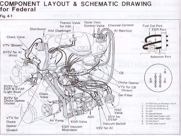
 
I stabbed the dizzy with the BB in the pointer and the button pointing toward the #1 plug on the dizzy cap and the both pointing a hair left of the #4 plug in the cylinder head.

Once I got her started the timing gun was set at 0. I adjust the timing by turning the dizzy till she was running smooth and had good power … also with good vaccum on my gauge.

I then slow moved the digital advance button up on the timing gun and when it read 18* degrees the BB was back in the pointer

What would the total timing be … 11 or 18
 
Still chasing a slightly hard to start
( inconsistent) issue but we are getting close. I did replace the coil ( didn’t fix the inconsistencies in starting) cause I found a OEM one super cheap…. Why not !!!

Few new questions …..

The dizzy has the 2 vacuum ports . The one closer to the dizzy body is for the vacuum advance. I believe the secondary one is for the
High Altitude Compensator which I don’t have or need. Should I cap it off or I have seen where some have split the vacuum line for the vacuum advance and hooked it to both ports . Any thoughts ?

Also I’m having issues with the carb’s secondary not opening under load or WOT. I confirmed it with the paper clip test

I removed the vacuum assembly and tested it by sucking on the gold valve and the diaphragm retracted and held in place as long as the suction was held. Once released the diaphragm released as it should.

I then used a hose and blew through the black gasket area on the carb ( where the gold valve lines up to it ) and could hear air blowing into the carb so the passage is clear.

I also could see the gold valve and black gasket area seem to line up but not perfectly ( see pic with gasket outline) Maybe the gasket is possibly blocking the vacuum flow ??

IMG_7959.webp


With the carb mounted and linkage hooked up, I made sure my throttle linkage is activating and freeing the secondary and it is .

So either the vacuum assembly isn’t lined up good enough and the vacuum can’t flow or either the carb isnt making vacuum to operate the secondary under load.

Both fully closed …. Zero throttle. I can see the primary blade ( top one) isn’t fully closed and has a slight opening. That correct ?

IMG_7963.webp


Full Throttle / WOT

IMG_7964.webp

IMG_7965.webp

Full throttle /WOT and the secondary linkage fully opened.


IMG_7966.webp


I’ve also attached a few videos of the linkage and butterflies operating. Anything look off ?

I’ve attached a few videos of the butterflies operating and the secondary linkage.

Secondary Linkage # 1

Secondary Video # 2
 
Last edited:
Not sure it matters but does the secondary open up too much on the WOT pic or does that really make any difference .

I also notice the primary doesn’t fully close when no throttle … is that normal as well. Seems to be a slight opening

Might post this secondary portion of thread in its own thread as it carb specific
 
Last edited:
 
Late to the party but you might find some info here helpful for getting your evap or other systems hooked up


The bolts or whatever were used to block off the air ports in your head should probably be checked. There is an OEM part available for those.
 
Update… new OEM carb installed. Vehicle starts, idles, run like a champ!!!! Very happy and thanks to City Racer for the great service !!!!

This is my movement on my secondary where before it would not move at all. I need to pull the cleaner assembly and test by hand to make sure this movement fully opens the secondary.
IMG_8035.webp


Now I’m gonna get to plumbing the charcoal canister and the ports for on top of the dizzy.

So for the canister this is the diagram I’m using
IMG_8064.webp


Canister….

IMG_8063.webp

1. Run a hose from the tank port on the canister to the separator behind the passenger seat in the B- pillar. Using the check valve (10020) below in the hose between the two.
IMG_8066.webp


2. The run a hose from the purge port on the canister to the VSV ( see below) then to a port on the intake manifold.
IMG_8065.webp


3. Then add a T to the vacuum advance hose from the carb to the dizzy. The hose from the T goes to the smaller port on the VSV. I assume that this opens the VSV while under throttle/vacuum allowing the manifold vacuum to pull the fumes from the canister into the intake manifold, reburn, then out the exhaust .

4. The unnamed port on the left of the canister…. Does that get plugged as I’m de-smogged?

This seem correct ?
 
Last edited:
Now for the Distributor Venting circuit ….. this is the diagram I’m using although a hair confusing …. Maybe!

IMG_8039.webp


IMG_7844.webp

1. Larger port goes into the cabin with a filter at the end. This is where the fresh and dry air is pulled from

IMG_8068.webp


2. Smaller port from canister is hooked to the VCV on the Z port ( larger black on left )

3. Manifold vaccum from intake is hooked to the S port. ( blue port / bottom ). Now I don’t have a gas filter in the intake, just a nipple so I may have to buy one if really needed.

IMG_8061.webp


4. Y and X ports seemed to be hooked to the air cleaner assembly … not sure if both are needed and which ports on the cleaner assembly to use as there are a few

IMG_8056.webp
 
Ok… so got everything hooked up….. seems to be correct. I’ll start with the VCV / Distributor Venting Circuit.

1. Got the OEM 2 port “ Gas Filter “ installed into the intake manifold.
IMG_8181.webp


2. VCV plumbed in. Top (Y) got to the passenger side port on the Air Cleaner. Left & Right ( X & Z ) make a circular connection then go to the small port on the distributor. Bottom ( S ) goes to the Gas Filter on the intake. The final hose goes from the large port on the distributor to the firewall port / in-cabin filter.
IMG_8187.webp


IMG_8178.webp

IMG_8179.webp

IMG_8180.webp


With no vacuum on Port S, you can’t pull or push air through Port Y,X,or Z. With the vacuum on Port S the air flows freely through the Y, X, and Z ports.
 
Last edited:
Now the Charcoal Canister.

1. Ran a line from the Fuel Vapor Separator in the B pillar to the Tank port on the canister. I placed a check valve in the line ( I should move it in the Fuel Separator compartment )
IMG_8185.webp

IMG_8182.webp


2. Then the hose from the Purge Port to the lower port on the VSV. Then the Lower Hose from the opposite bottom port to the Gas Filter. The smaller upper port is the connected to the split hose for the vacuum advance.

IMG_8183.webp

IMG_8184.webp


So when the vacuum advance kicks in.. it opens the check valve allowing the vacuum from the intake gas filter to pull vapor from the purge side of the canister. I did plug / cap the 3 port which used to go to the Outer Vent Control Valve but being De-Smogged is not longer present. Not sure if I should plug this or leave it open

I’m also added a tach ..
IMG_8186.webp


If it looks like I missed a step or got something wrong please let me know.
 
Last edited:
Can anyone advise what this does? It’s on the inside of the air cleaner assy. It has 2 nipples on the bottom that are open to the outside air and mine had a short cut hose attached to one. Should I cap both nipples or leave it open ?

IMG_8197.webp

IMG_8198.webp
 
No clue what it did in pollution control system. Its letting in a very tiny amount of unfiltered air.
 
Which of these looks correct for the final dizzy location. The black mark to the left of bolt hole is where the #1 wire is located .

This is a large cap FJ60 dizzy setup

IMG_8252.webp

IMG_8247.webp
 
Back
Top Bottom