Alice in Chains build (2 Viewers)

This site may earn a commission from merchant affiliate
links, including eBay, Amazon, Skimlinks, and others.

MC 07 xd showed up on my door step today.:clap:

After doing some research I've decided to make my own triple stick set up. It will be similar to the one Davez Offroad has with a slight twist, I want all my sticks to be in the rear position when in high/high/2wd. There will be alot of changes to come to accommodate the new twin cases but I'm sure I can retain the stock 4runner console with just some trans tunnel modification.

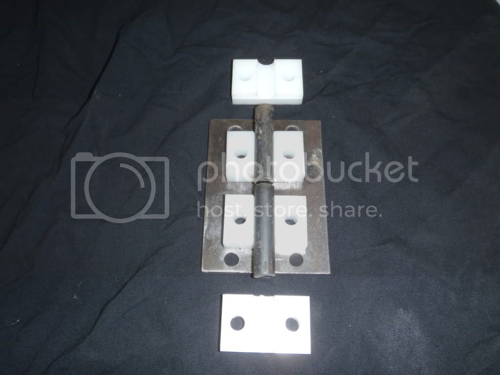
I had saved some hard plastic blocks some time ago and don't remember what they were even for but they will be great for rear case set up. here are some picks of the base plate,blocks and pivot rods along with the pattern for the lever arms in side the case.

PC290129.jpg


PC290130.jpg


PC290133.jpg


PC290135.jpg


PC290138.jpg
 
Thanks!

Some more progress this morning plus a little modification for bolt clearance. I will be getting some allen head bolts and do a little grinding to help as well.

PC300140.jpg


PC300141.jpg


Pivot rod assembly and lid soon to come.
 
... not as far as I wanted but it's still progress.

PC300142.jpg
 
Getting closer...

PC310144.jpg


PC310143.jpg


PC310145.jpg


PC310147.jpg


but ran into another issue.

Two of the lid retaining bolts hit the case inside but it can be remidied by flipping those two and making them studs instead. After a little grinding it will clear just fine. The two nuts for the others will be welded to the bottom plate as well, wouldn't want those falling into the case.
 
Looking pretty slick there, Bill! To be honest, I had no idea what the fxxx was going on in those first few pictures.... Hope to see this thing in action soon.
 
awesome ,your saving some folks alot of money and time in the future.

If you have demensions and or any info for future readers that would be awesome.:cheers:
 
Soon? :lol:
Could be ready for a spring run I suppose.
This is going to require trans tunnel, console mount, cross member,transmission mount and drive shaft mods, along with that I will fix my floor pan at the rear of the cab so...

I'm really looking forward to double low, I'm sure my clutch is too.
 
awesome ,your saving some folks alot of money and time in the future.

If you have demensions and or any info for future readers that would be awesome.:cheers:

I'll work on redoing my original drawings and make a list of the tools I used as well.

For now few more pics, the first has the ground down bolt heads for the clearance needed to clear the case housing. I left about a 1/6th inch of the head on the side that was ground to keep the bolt from pulling through. These bolts and nuts will also have lock tight applied do to the light torque needed. To tight binds up the movement of the shift rods.

P1010149.jpg


This pic shows a mark I made with with the cut off wheel to be able to line up the parts after notching for welding.

P1010152.jpg


These two pics show the 3/16th deep notched sides of the round stock for good penitration of the welds.

P1010153.jpg


P1010154.jpg


I debated myself as to weld these parts on or to take the time to create a keyway, drill and tap for a removable part. I went with the welding to save time.
 
The reason for having to grind the heads of the stud bolts.

P1010006.jpg


Twin stick finished and mounted.

P1010007.jpg


P1010008.jpg


The tools used.

P1010002.jpg


P1010003.jpg
 
Revised drawings, some of the numbers are not there but everthing was figured from center.

P1010027.jpg


P1010025.jpg


P1010026.jpg


P1010024.jpg


My dial caliper was the primary source of measurements.

This end works great for finding the depth of holes but due to the machined surface by the pivot ball it gave me the depth needed inside the case.

P1010009.jpg


P1010010.jpg


After verifying a square corner it was marked and all dimension were pulled from those two sides only.

P1010013.jpg


P1010014.jpg


I left the center point of the half inch hole on the pattern to use as easy way to mark the steel with my center punch.

P1010015.jpg
 
The 45 deg corners were never measured or calculated but rather just cut to allow enough clearance for the bolts. always some issues with a fist attempt.:doh:
 
Dude good build and way to step out of the norm with the carb and the shifter and shoot even the crossmember! Its easy to do like me and follow everyone elses leed but you are not afraid to blaze your own trail!
 
Thanks, it's pretty much do to the fact that I'm a mega tight ass. I also enjoy the challenge.

It has been said that I can pinch a penny until the Indian comes out riding the buffalo.
 
It may be a little while for an update due to mandatory over time.
I've run out gas for my welder and everything is closed by time I get off work. Ah, the pleasure of living amongst the corn.
 
Alice finally got new shoes, and ones that fit!

BF Goodrich 35 x 12.5 x 15 KM2's on Mickey Thompson classic II's
Also picked up a BFG AT full size spare at a swap meet.

image.jpg


I'm going to get started on the cab repairs and floor mods this weekend.
 
I got the bed pulled off for access to the cab and took some pics to show better detail of some of the other mods.

The rear bumper is in need of repair...

P4060104.jpg


didn't quite make the climb and slid back into a tree. I will add some additional brakets to attach the two outside ends to the bed as well for added strength for when it happens again.


A good shot of the spare tire clearance, only the sidewall is lower than the frame.

P4060101.jpg


Belly shot of the bed. Outside of the main 2x2 tubing you can see the bed linner sections that help keep the bed boards cleaner.

P4060108.jpg


Shots of the dual battery trays, shock mounts and fuel cell.

P4060105.jpg


P4060107.jpg


P4060106.jpg


Rock sliders mount without the use of additional plate because of the "I" beam sections I used for gussets which spreads the load across the entire height of the frame.

P4060113.jpg


P4060115.jpg


On to the damaged cab...

P4060109.jpg


P4060110.jpg


rust and a few years of trail abuse have begun to take there toll. The plan is to reinforce the seam connecting the floor and rear body panel and rear body mounts.
 
The remains of a rotten single cab parts donor will make the rear body panel. I am flipping this section upside down to utilize the window opening reinforcement to connect the rear body mounts.

P4080117.jpg


When I am replacing body panels I use an air cutoff wheel to "erase" the welds on any panel not being saved. It is less time consuming and easier on the elbows and shoulders than drilling. Controling the speed of the cutoff wheel is important because if you use full speed it is harder to notice when the panels show seperation.

P4080120.jpg


As you can see when done right all of the backing panel remains intact.

P4080126.jpg


Using tape to make the final cut line, I usually mark with an arrow which side to cut as well just for reference.

P4080125.jpg


Some modification of the cross member is necessary for my plan of making the rear section of the floor flat for more storage.

P4080129.jpg


P4080128.jpg
 
Floor's cut and I'm adding a piece of 1" square tubing to the front of the rear body mounts that I will plug weld the new floor section to as well.

P4080130.jpg


A section of a Suburban roof that will become the floor pan. I don't have a bead roller (and I'm cheap) so I'm using this to gain the stiffening ribs.

P4080131.jpg
 
I decided to add some additional support to the seat mount crossmember. The flexing of the cab has ripped some of the spot welds loose.

P4150135.jpg


Using a section of the original floor that was cut out I made a nice transition to the new floor pan. By turning it around it now turned down to the new supports.

P4150134.jpg


Welded in and ready for the floor pan.

P4150137.jpg


Cutting the roof section to the ruff dimensions I just scored the panel with the cut off wheel and bent it on the scored line to keep from using more cut off wheels than needed.

P4150140.jpg


P4150142.jpg


First trimming and shaping to match the center hump after finding center of the reinforcment ribs.

P4150144.jpg


After all the trimming and shaping was done it was ground clean for welding and coated with Aluzinc from the Wurth Co. I Like this brand better than 3M due to less clogging.

P4150146.jpg


Welded in.

P4150147.jpg


A comparison of the floor space gained.

P4150148.jpg


P4150149.jpg
 

Users who are viewing this thread

Back
Top Bottom