1970s 40, 350/TH350 on Megasquirt 1 PCB3.0 (1 Viewer)

This site may earn a commission from merchant affiliate
links, including eBay, Amazon, Skimlinks, and others.

Joined
Mar 27, 2013
Threads
70
Messages
1,225
Location
Sedro Woolley, WA
Figured I would start a new thread as some may be interested. I personally wouldn't consider this 'hardcore' but I'm guessing some will, and what is difficult for some is easy for others. (Apparently getting a quadrajet to run right isn't so easy for me).

The vehicle - 71 frame/tub, long term project
Late 70s 350 4 bolt main, supposedly has cam, MSD dizzy, edelbrock intake.
TH350, stock transfercase

I was planning to swap in a GM TBI system I bought with a 305... however as it turns out, I simply can't easily retrofit the 1991 305 ecu into the 350 I have... I have some concern with the knock sensor, I'm missing the AIT sensor, some concerns with the VATS system in the ECM I have, and some concern with all the extra wiring/stuff that comes with the stock system.

I was also concerned with the down time that would be associated with trying to retrofit the system to an older 350 or having to swap in the 305.

I have experience with MS...

First experience I had was way back in about 2004 - I built a 1987 MR2 hardtop with a JDM 4AGZE, retained the supercharger, and went with MS1 PCB 2.2, with a relay board and EDIS4. It was great, except that the PCB2.2 has issues with low impedance injectors - and lo and behold, I blew injector fets from time to time. That was a fast and incredibly fun car. As far as I know I was the first to MS a 4agze and retain the SC (most guys went turbo back then... in fact the original MS & Spark was designed/built by a local MR2 guy).
PIC00064.jpg


Helped many others get their cars up on MS.

My second car on MS was... oddly enough... a 1987 MR2 (T-Top this time...
I've had 11 MR2s, only 2 1987s, both got MS). MS1 PCB3.0. Much more stable with the injectors. That motor was a 7AGE (technically doesn't exist... it was a small port 4age head with a 1.8L 7afe block, high compression 4age pistons... and was around 11.5:1).

Both vehicles were built with the engine and MS in mind - meaning neither were run on a computer with that engine other than MS.

After doing some reading I came across a post regarding MS and a TBI unit on an older 350 - what I liked about it, is that they discussed being able to install I steps - basically get the MS working, wire up to the tach and various sensors... but still running on the carb. Basically testing/tuning without any actual changes to the vacuum dizzy and carb.

To me, this means far less down time. Meaning, the MS will get built (I'll provide some photos when it arrives and what is entailed... I ordered the kit, an unassembled kit), then partially wired, then will get fuel, and when I'm ready, will swap the dizzy to have full electronic control.

This will be the first time I go MS without a relay board and without EDIS....

First step, once it arrives, will be to build the MS.

Next will be to install:
AIT (I have a spare Corolla unit)
CLT
O2 sensor
Wire in the tach

After that is all working I will:
Install the External Fuel pump (Carter P5001 on order)
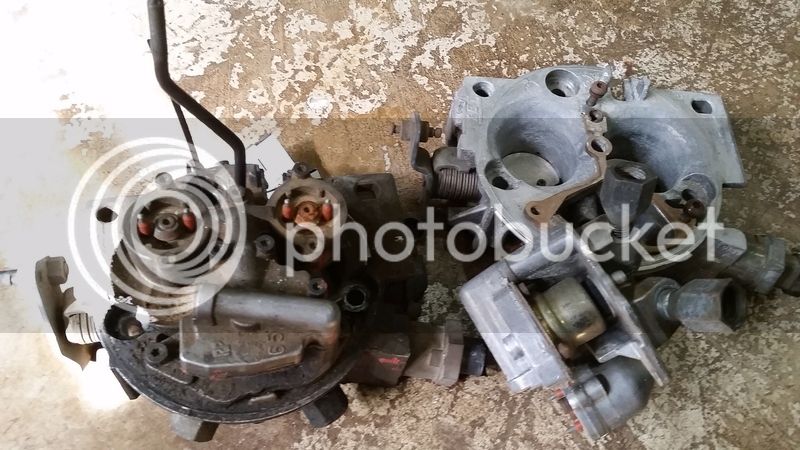
Install the TBI (which will include injectors, IAC stepper motor, and TPS)
Fire it up

After that (and probably won't happen until winter) will be to get it up on spark control ad well. That may require a few configuration changes to MS and some down time.

I went this route because whether there's a 350, 305, or some day go back to an F motor (I've poked at the idea of a 1fx swap), the MS can handle it all with minimal changes.
 
MS kit arrived. Got my solder station out of storage....

The kit assembles pretty easily (when your iron works).... a couple tips.....

If you use the small tube type solder, drill a hole in the top - it makes holding and feeding the solder SO much easier and faster....
20160701_091154_zpszomww3mw.jpg


You want to use an iron, not a solder gun. My station was basically useless (was able to get the DB9 and DB37 cable ports soldered, but nothing intricate). Radio Shack didn't sell tips for my iron, so I bought a dual 15/30w iron (the station was an adjustable up to 40w iron).

This is what the kit will look like when you receive it... I will post some photos when I get some more time to work on it...
20160701_090546_zpsyhskui8n.jpg


Edit... forgot to mention. ....

Have a small screwdriver on hand to put into the ground of an electrical outlet while holding the metal. I know this is probably against what you were taught as a kid, but (so long as your house is wired properly) this will remove static electricity from you/your hands and reduce the chance of ruining electrical components...
 
Last edited:
Not sure I'm with you on the why... but no matter, I can certainly see the benefit of being able to account for a wild cam and the ability to tune on the fly. With that said, once the system is fully up and running, fill the motherboard/case with impact silicone. You won't be able to fix it should something go wrong, but something will go wrong in a 4x4 application if you don't fill the board.

I have a MS3x, it's for my twin turbo Buick, my Fiat uses the 2nd gen (obd2) computer because it can be tuned pretty readily, but as you know, I went with the stock OBD1 TBI system because they're dead nuts reliable...
 
I had issues with pcb 2.2 primarily because the injector drivers were oddly mounted to the case and I was using 4x 365cc low ohm injectors, which overheated the drivers.

PCB 3.0 was running those and then different injectors no problems...

Both personal vehicles that I set up - built the MS, wired, and first attempt fired up.

MS1 is a simple system and will be perfect for TBI. It removes a lot of extra/unnecessary wiring... it will not need me to either completely take apart and rebuild a harness to fit into the 40 nor try to retrofit a chevy harness into the 40 body (and many wires being too long or short).

It will allow me to choose how exactly o want to wire everything... like fuel pump relays, ignition circuits, separate fan controls, etc.

It will also be much easier to diagnose issues than a stock TBI. I've read other board members who have to do a lot of eprom burning to get it right. I know another 40 owner who is constantly having poor fuel mileage yet never throws a code, and has thrown who knows how many parts at it to fix, yet can't seem to resolve the runability issues he had.

Since I'm wiring and building it all, I will know what's going on with it should something happen. There's very little internally that's any more susceptible to damage in a 4x4 than any other ecu except the crystal, which is already recommended to hot glue down. I also plan to use velcro to hold the case to the body in the glove box... so that it's mounted, but isn't a solid mount and can absorb some shock.
 
Unit is built.

This is actually the first time I've "followed" the instructions...

It seems that the tests for it are all good, as expected. I've never done fuel only, so I'm guessing my (old) stim board that I've now converted to 9v battery isn't running rpm as expected because the MS is built for -coil right now. Without even running boot to load the new systems my old (old... Fujitsu stylus 3400) laptop that has been a 'garage' laptop with an old copy of Megatune registers the MS and many of the inputs no problem.

20160703_115143_zpslfxmyjwx.jpg


20160703_115203_zpsswfbqwtb.jpg


I will say that the radio shack iron.... sucked. Heat was great, the tip for anything intricate was terrible. I actually found myself soldering a couple legs together here and there and spending time undoing that. It took a bit of extra work and time to make it all work.

Now I plan to build the DB37 cable... I'm thinking 1' sections, label them, and then wire as I go/need....
 
For anyone who is following... I got hung up on the testing phase.

The build page they have is here:
MS-Extra V3.0 Build Manual

At step 26 (oddly enough, the 2nd step 26) it mentions how to build the ignition circuit.

I'm going -ve for now, just using the existing coil and will play with spark later...

The step that talks about the 36v zener diode backwards - #1, the diy kit comes with a 22v zener (and no, radio shack doesn't stock a 36v unit). I forges ahead and used the 22v.

Every test worked perfect. Stim powered up, I was able to try varying versions of firmware (and load them).... but I couldn't get an rpm signal from the stim board.

The purpose of the zener is to accept the coil negative signal, but to block the system from high voltage input. So when testing with a 9v/300ma adapter or 9v battery and the stim... there isn't enough signal received and the zener has to be byppassed.

Once I jumpedthe zener legs (D2) the 'injectors' in megatune/stim came to life.

Time to start wiring, I guess!
 
Just talking to myself - it happens though.

Been searching for wiring diagrams - interestingly enough there are diagrams for the V2.2 board and negative coil driven but not so much the V3.0 boards.... probably because the V3.0 boards do more, and those who want more are probably using ignition.

This is what I have been using/making notes on (printed) to prep some simple wiring:
MegaSquirt-wiring-diagram-thumbnail.jpg


So, decided to dive deep into the mega manual - in the build sheet I found the answer - which is pin 24 runs to the coil. Upon further reading it talks about issues with noise and that the signal grounds back out through XG1 to the XG2 jumper, which connects the internal grounding systems.

See here, step 52:
Assembly Guide - MegaSquirt(R) V3.0 Main Board

It says to clip/remove the jumper, connect XG1 to one of the spare DB37 connectors (1 of 4 spare outputs... so this is still an internal jumper) then run a ground back to the distributor/coil.

It also mentions to do this for noisy hall sensors (which when I do go ignition, I will be using).

To make things even easier, the shielded cable I have is 2 wire wrapped shielded cable.

The only time I would need the XG1 jumper is for using the stim....

I don't have any current plans for the other 3 spares, so losing 1 of 4 isn't a problem.... seems like a preventative step to smooth out possible issues....

As a side note - in the MR2s I had issues with noise and the VR sensor information to/from EDIS if I wired through the relay board - the solution I had was to bypass the relay board with the shielded cable running directly to the DB37 on the MS unit (which in the first photo above you can actually see)
 
So for anyone on the edge of their seats here..... been a busy week not on the 40... family visits and work have consumed most of my time. However....

I did the XG1 to spare 4 modifaction.

I started to build a short harness I can work with. When dping this, be careful to ensure no wires or solder bridges between pins. As shown, it's also a good idea to use heat shrink tubing. I put the db37 into a vice just tight enough to hold - then generally prep the wire with solder, then hold the wire in place on the db37, allowing heat to transfer solder from wire to connector. Give a little tug before moving to the next... then when done, shrink tubing.
20160708_220045_zpsf9aips3v.jpg


I already have a separate fuse panel in the build of this trick, so I'm opting out of the megasquirt wiring for power. Instead of 2 relays into a fuse panel, I'm going with a fuse panel into 3 relays, and already have a switched/fused ignition circuit for the coil.

There is a "main" relay that kicks on with the key (fused at 20a) with 2 outputs - one to the ecu (with a fuse between) and one to the other 2 relays (sorta daisy chained). The 2nd relay will power the injectors, and 3rd the fuel pump (the power in to each relay is separately fused).

As a side note - the main wiring for the relays in the mega manual are wrong. They show a 4 pin relay so it isn't as much of an issue, but the 30 pin should be the input, as 87 and 87a on a 5 pin are outputs (87a switching power when the signal 12v is off).

The mega manual also states to run the grounds direct to engine-I skirted around this - I ran a ground to a bolt on the firewall that goes through into the glovebox, the ran the MS grounds to that. Since the battery is behind the passenger seat and grounds to the body/frame there anyways, I'm guessing this is as good of a ground as direct to engine.

The MSD dizzy I have has a ground and coil wire that I tapped the shielded cable to.

So far the wiring seems to be good - this shows the MS in the glove box, powered by the truck, and receiving an ignition signal while running on the carb:
20160714_193447_zpsty7vha4m.jpg


Now to start wiring the rest. In doing so, I keep running into small issues. The idea is to get as much done before the fuel pump and TBI go in, while still able to drive on the carb.

This is an AIT from a 90s corolla -used them in the past and if they vary from a chevy unit, it's almost a nil value. Bored a hole in the air filter housing out and it's hidden out of the way:
20160715_154733_zpshlben0cd.jpg

20160715_154948_zpsknztala4.jpg


Wanted to test fit this on the TBI - turns out in all the boxes of crap, the air filter mounting for the tbi is missing. Among many small bolts/screws - so I ordered another TBI and it's on the way. Hopefully it also has the collar, as I did request that piece too.

Prepping for the coolant temp sensor has been a pain. No photos.... the best place I feel comfortable with is in the manifold - however the port is under the t-stat/water outlet housing. A simple brass fitting (1/2 to the CLT 3/8) doesn't fit. Tried a 1/2 90*, doesn't fit. So I also now have a taller, rotating water neck on the way.
 
No dice on the collar, and the tbi looks filthy. However it's otherwise complete and my highly accurate testing of the injectors (by hooking up to a battery) gives an audible test that makes me like/trust these injectors far more than in the TBI unit I have (in the first unit I had to massage them just to work). I have a TBI "rebuild", aka gasket and pressure regulator diaphragm, kit and will give some photos when I do that. The other unit also had a partially broken fuel inlet or outlet line - which short of smashing it inot something I have no idea how that was managed.

Some other gathered items... the transdapt adapter will let me use the edelbrock manifold on my current 350... it's build is 'meh' but will suit the purpose.
20160729_101236_zpsvmjk9ind.jpg

Not shown is the O2 bung that will hopefully go in very soon.

'New' on the left.... as clean as the unit on the right is, it's missing parts and as you can see, has the broken fuel line inlet:
20160729_101136_zpss7f8bkc5.jpg


Looks like some modifying of the hold down screw is needed, otherwise I like it with the 2" adapter and every thing has clearance.
20160729_101444_zpsp9mw7ssv.jpg


Although my progress has been slow (it should really be running on it by now, but I've only spent a very short amount of time on it recently), it will probably get even slower... heading out to rent a good 220v Miller welder so that I can get at least the rear of the cage built, and the bikini on it.
 
Forgot that this got done... I'm not overly happy with the upper hose, but with varying radiators, locations, (and more) I think I may have exceeded record on the new upper radiator hose replacement to miles driven ratio (I'm somewhere around having to buy 6 or 7 new upper hoses alone at this point in the vehicles lifespan with me, and it has maybe 25 miles on it with me).

20160729_103502_zps0dlmzex4.jpg


Taller/rotating water neck installed to give clearance for the coolant temp sensor and brass fitting.

In an unrelated note, I did get the adjustable radiator fan relay installed....
 
Another month and not a whole lot of progress. Most of my spare/car time went to the cage/Sliders for the 40 and the starter/battery/wiring issues on the 80... recently I also got the adjustable fan control relay system installed, on a switch, so I can shut it off at will, but also have it self controlled based on temps....

Will get pics soon, but... I did pull the driver header (turned into its own fun nightmare since the header/exhaust/muffler went on in one piece with the fender off originally) and install an O2 bung with a one wire sensor.

I also had an AC Delco "rebuild" Kit for the TBI... as it turns out the 2 units i have are ever so slightly different.... and wish i had taken a photo...

once the injector/regulator housing was off, one of the holes in the base of the unit was different (and this was where the air filter stud screws in)- the light colored unit had a set screw that screwed in, but sat slightly above flush from the base. This also changed the shape of the gasket between the base and the injector/regulator housing.

This wasnt a big deal, though, as the Delco kit had s*** paper gaskets and stock appeared to be of a pseudo phenolic material, so I used that original gasket.

I did replace all injector seals, the regulator (which is interesting), pulled electronics from the base and gave it a purple power bath (or Castrol super clean... whichever I had) before re-assembly.


The only question/potential issue... it looks like the "resting" phase of the IAC motor is pretty darn wide open... I wasn't planning on including that quite yet with the MS, so I may look into some way to trick it, and maybe even set it up as some sort of on/off choke system for now.
 
Couple things when I put mine together. The TBI body was warped. I had to sand the base on some MDF to get it super flat. Second was the throttle shaft. It was worn enough to need a rebush. I bought a kit and did that myself (have enough for 4 more TBI's). From what I have read the auto parts rebuilders rarely do that so even a rebuilt unit might leak air past the IAC.
 
Interesting, I'll have to throw a straight edge under it and see how it looks. Considering it's bolting to the mediocre adapter which then bolts to the edelbrock manifold I have, I won't be surprised if there's a vacuum leak. Luckily I'll pull vacuum from the manifold and the system is map based, so won't be all that sensitive to vacuum leaks like an AFM system is (like an early 80 series).
 
Update is that we spent time getting it cleaned up (roll cage painted, cleaning wheels/paint for the first time, redoing the front seat backs) because it was the vehicle we 'drove off' in for our wedding in September. I didn'twant to pull the carb and mechanical fuel pump and not have time for it to be roadworthy. Then in Hawaii for a week, then played host to family for another week, then re painted/new floors/fixtures in our sons room....

Updates are that I've pulled the appropriate connectors from the 305 harness I'll need (TPS, Injectors, IAC).... I've also thought about fuel pump placement and trying to decide what to do for fuel lines, pump placement, and whether I want to pull the passenger seat (although not a big deal, I recall 2 of the bolts have very minimal movement and take 10 min or so each, so a nuisance)...

I went with MS1 because I personally don't need the features of MS2 or the MS1 + daughter board. Its a simple setup with minimal input/outputs. Simplifies the wiring and any potential diagnostics if anything goes wrong during or after the build. I went with the V3 board because it's injector circuits are better protected/robust than the 2.2 board. In my very first MS setup (ahem, about 10+ years ago) the injector drivers blew out on low ohm 360 cc/min injectors.

If it's something you're considering I have no problems providing assistance if/when possible. I always recommend buying a kit and building your harness (whether you use the relay board or not is up to you) so that you understand the system better. Most people who fail with MS have little understanding and unwillingness to learn/understand even the basics of it. DON'T assemble using a cold heat solder system.
 
I'm still debating using MS on a scout project that is coming up. But since it's a 4.3 TB. The general computer can be had cheap and burned fairly easily..
 
I found it hard to figure out what I needed for a simple old school TBI. I ended up modding a factory computer with a removable chip, chip burner, etc. In the end I think I spent more money than I would have with an MS and regret not going that route.

Update is that we spent time getting it cleaned up (roll cage painted, cleaning wheels/paint for the first time, redoing the front seat backs) because it was the vehicle we 'drove off' in for our wedding in September. I didn'twant to pull the carb and mechanical fuel pump and not have time for it to be roadworthy. Then in Hawaii for a week, then played host to family for another week, then re painted/new floors/fixtures in our sons room....

Updates are that I've pulled the appropriate connectors from the 305 harness I'll need (TPS, Injectors, IAC).... I've also thought about fuel pump placement and trying to decide what to do for fuel lines, pump placement, and whether I want to pull the passenger seat (although not a big deal, I recall 2 of the bolts have very minimal movement and take 10 min or so each, so a nuisance)...

I went with MS1 because I personally don't need the features of MS2 or the MS1 + daughter board. Its a simple setup with minimal input/outputs. Simplifies the wiring and any potential diagnostics if anything goes wrong during or after the build. I went with the V3 board because it's injector circuits are better protected/robust than the 2.2 board. In my very first MS setup (ahem, about 10+ years ago) the injector drivers blew out on low ohm 360 cc/min injectors.

If it's something you're considering I have no problems providing assistance if/when possible. I always recommend buying a kit and building your harness (whether you use the relay board or not is up to you) so that you understand the system better. Most people who fail with MS have little understanding and unwillingness to learn/understand even the basics of it. DON'T assemble using a cold heat solder system.
 
I found it hard to figure out what I needed for a simple old school TBI. I ended up modding a factory computer with a removable chip, chip burner, etc. In the end I think I spent more money than I would have with an MS and regret not going that route.

I think the pricing comes from where you source parts... I went the expensive route and wanted a stock TBI system... Bought a 305 with trans/case, harness, and computer for $400... and the more I got into it the more I hated it. Overly complex for a simple system (the 305 harness is probably 10x larger than the MS harness will be), the TBI it came with was incomplete, some sensors missing, pieces I paid for that I don't need. Although the 1990 305 isnt a great motor, I'm guessing it's better than the tires 70s 350 in the 40 (so I have a spare V8).

MS was around $200, solder $5, iron $10, wire I already had. I ordered another TBI for $60 and making everything else work. The TBI kit was $25 on Amazon and with 2 TBIs I can choose my injectors. I paid $80 for a dizzy but don't plan to incorporate that until later.

The pump was about $100 and needed either way. I had to get an adapter for the TBI since I can't use the 305 with my headers/exhaust (the 305 has the longer bolt pattern on one end vs the early SBC heads) so currently have to use the 350. I consider the pump a cost for either, so not attributing either way.

So I'm around $400 for the MS specific parts. I have an old (I mean OLD) "tablet" that runs Win2k that works with MS.... so can keep that on hand.

The issues SBG has had with his 'stock' TBI is partially exactly what I foresaw (read first few posts) and is why I thought MS is a way better route.
 
I'm still debating using MS on a scout project that is coming up. But since it's a 4.3 TB. The general computer can be had cheap and burned fairly easily..

If you build and wire MS yourself.... not only do you get the accomplishment of doing so, but you know the system. It's easy to diagnose and is transparent.

As I said... if I decide I want a different engine I can reprovision it/sensors, burn/tune in the fly, and not even rewire the vehicle. I have seriously considered going back to an F motor, and could easily make it EFI without much rewiring, while retaining the MS.
 
Last edited:

Users who are viewing this thread

Back
Top Bottom