Upgrade RS3000 to other alarm without going under the dash. - Tutorial

This site may earn a commission from merchant affiliate
links, including eBay, Amazon, Skimlinks, and others.

sbman

Supporting Vendor
Joined
Apr 19, 2015
Threads
40
Messages
1,503
Location
Julian, CA
I wanted to upgrade the RS3000 factory/port installed alarm to something that I can actually use. I have never had a FOB for it and have read so much mixed stuff about it that it seemed good to just replace it. I don't like alarms much anyways, I just want keyless entry. I have been afraid it would 'arm' itself at some point and disable the starter.

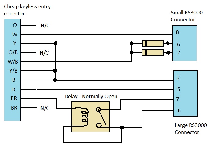
I also did not want to create a new wiring harness and tap into all the circuits again, the factory RS3000 harness does a nice job of that. I could not find a full pin description for all pins in the harness though.

To be clear, the RS3000 should be installed under your drivers seat. You will need to remove the seat to get good access to it. 4 14mm drive bolts will remove the seat, as well as the power seat connector if your truck is so equipped. Just tip the seat back once it is loose, and squeeze the connector top/bottom and pull to remove.

So, with the seat out of the way, unplug the three connectors on the RS3000, cut the zip tie holding it down and remove it. Get it on the bench and open it up. Four screws and 4 plastic catches hold it closed. You don't need to be gentle, we aren't re-using it.

IMG_6591-L.jpg
 
Last edited:
Now that it's on the bench, we need two parts off of it, the two large connectors. Get some small narrow pliers, cutters, and screwdrivers.

Start by cutting the pins on the larger connector. Leave plenty of tab left for soldering wires to later.

IMG_6592-M.jpg


Cut the bottom row as well and you'll have all the pins loose. The screws holding it to the board are soldered in place. Get your pliers and start breaking the board away until it comes free.

IMG_6593-M.jpg

IMG_6594-M.jpg


Once it's free, use your pliers to clean it up. Nice.
IMG_6595-M.jpg


Don't feel sorry for the RS3000. It's 4 bit processor is living in the 64 bit age. Think of it like an organ donor.

Do the same thing for the other smaller 10 pin connector.

IMG_6600-M.jpg


Some of these pins were going to be very short if I just cut them. I decided to de-solder some of them. To do this you'll need a soldering iron, some solder wick, flux, flux brush and some patience.

You want to heat the solder on the pins through the wick, and it will suck up the hot molten solder. It takes a bit of practice and some persistence.

IMG_6597-M.jpg


Do some more breaking and get that connector off of there! I needed a relay, so I de-soldered that too.

IMG_6604-M.jpg


If you need a relay, it's free at this point. Plenty of diodes on this device to re-purpose also.

IMG_6603-M.jpg
 
Last edited:
Here is the key. RS3000 factory harness pinouts!

There are three connectors under the seat, a large 10 pin connector, a small 10 pin connector and a small 4 pin connector (which I'm ignoring because it's just the antenna wire).

The pinouts reference the free '96 EWD schematics by page number/diagram number and connection point. Color codes for the wires are given. L=blue, B = Black, R=Red, Y = Yellow, W = White, G = Green, Br = Brown. First color code is main color, second code is stripe color.

The large connector has the following pins:

  1. Pin 1 B/L Starter Cut Relay Control. I believe you need to put power on this pin for the starter to be enabled. It may need ground though! I'll be testing this shortly and update here.
  2. Pin 2 W/B Ground. Connects to IE1-6 Diagram 6
  3. Pin 3 R/L Front Interior Light. Apply ground to activate. Dome switch must be in 'DOOR' position for light to light. Connects to IE1-3 Diagram 6
  4. Pin 4 R/Y Rear Interior Light. Ground to activate. Dome switch must be in 'DOOR' position. Conects to IE1-4 Diagram 6
  5. Pin 5 L/Y Continuous power. From dome fuse (10A) PWR Source. Connects to IE1-2 Diagram 6
  6. Pin 6 W/B Ground Connects to IE1-6 Diagram 6
  7. Pin 7 R/B Parking lights. Ground to activate. Spliced into light retainer relay 8 pin connector. Connects to L1-5 Diagram 3
  8. Pin 8 G/R Horn. Spliced into 14 pin combo switch. Ground to sound horn. Connects to EA1-1 Diagram 14
  9. Pin 9 Br Panel Alarm indicator. Apply power to light the light on factory alarm indicator panel. May need current limiting resistor.
  10. Pin 10 L/B Switched power, on with IGN position. From gauge fuse (10A). Connects to BJ2-8 Diagram 14
The small connector:
  1. Pin 1 B/Y Unlock. Pulse ground to unlock. Will unlock doors with the door open but not when it is closed. To use a single 'negative pulse' output from a standard alarm you have to connect this and pin 6 both to the output with isolation diodes. This is the unlock switch that detects when a key is used to unlock the door. Connects to BJ2-3 Diagram 15
  2. Pin 2 Not connected.
  3. Pin 3 Not connected.
  4. Pin 4 R Chirp +
  5. Pin 5 W/B Glass break module - Ground
  6. Pin 6 L/O Door unlock detection switch, front right hand. Grounded when the passenger side door is unlocked. To use a single 'negative pulse' output from a standard alarm you have to connect this and pin 2 both to the output with isolation diodes. Connects to BJ2-2 Diagram - 14
  7. Pin 7 G/R Lock. Pulse ground to Lock. Will only lock doors when ignition is OFF. This is actually the lock cylinder 'lock command' detection switch that is triggered via the key. Connects to BJ2-7 Diagram - 14
  8. Pin 8 R Glass break module - Power
  9. Pin 9 Y Glass break module - Signal. Did not test this, probably pulses ground when detects glass break.
  10. Pin 10 R/B Ignition key detect, Grounded when key is in ignition. Connects to I12-10 Diagram 17
This pinout is the result of many hours of dis-assembly of the harness and evaluation of the electrical wiring diagram. I can't guarantee it's 100% accurate, but I have tested most of the connections.
 
Last edited:
With the last post, I detailed the pinouts for the two RS3000 connectors. Now I will show how to connect a simple keyless entry system to that harness. You can do what I did and break the connectors out for a clean plug-in installation, or you could cut the connectors off and hard wire it. I chose to use connectors.

First, I bought an inexpensive keyless entry unit that had good reviews on amazon for $16 and free shipping. Yes, $16. They even delivered it on Sunday for that price!

Amazon.com : Docooler® Car Remote Central Lock Locking Keyless Entry System with Remote Controllers : Vehicle Alarm Accessories : Electronics

I figured out the schematic for the harness adapter and sketched it out.

KeylessEntryHarness.jpg


The schematic depicts the keyless entry connector on the left and it's wire colors. The two diodes were harvested from the RS3000, they are the same type of diodes that @NLXTACY sells for a window mod. You put the bands towards the keyless entry side. The relay I also stole from the RS3000, but you could use any 12V automotive relay. You will need to examine your particular relay and find the Normally Open switch to wire to pins 7 and 6 as shown, along with looping the pin 6 over to one side of the coil of the relay.

The reason you need diodes is to provide a 'negative pulse' to two signals on in the landcruiser at the same time. This defeats a feature that disables the power door lock switch when you lock the vehicle with the key. The diodes isolate the circuits from each other to prevent them from interfering with the standard landcruiser lock logic.

The relay is needed for the light flash pulse. The cheap module outputs a 12V signal to trigger the parking lights, but the landcruiser needs a negative signal. The relay circuit shown swaps it from positive to negative pulse.

In this form, you will unfortunately have to go under the dash and unplug the T-harness in the 11 pin combo switch under the steering wheel, and then re-join the factory harness. I'll work out a way to bypass that also so that you don't need to go in for that either. Will modify this post once I figure that portion out.

The diodes are wired like this

IMG_6608-M.jpg


The completed harness adapter.

IMG_6611-M.jpg


Installed and functional!

IMG_6612-M.jpg


I plan to put a more advanced unit in later that can turn on the dome lights and provide some nicer features.

Overall this cost about $18 plus a boatload of time to figure it all out.
 
Last edited:
.
 
It is very, very simple to completely remove the whole system & the wiring. No need to make new harness or anything. Everything just unplugs & you're done. Took me <30 minutes from getting tools together to everything put all back together.
 
Oh, I see. I never could get a fob that worked with my alarm so I just removed it all.
 
So you're basically going to solder wires to the pins so the new system can plug into the original harness?
 
So you're basically going to solder wires to the pins so the new system can plug into the original harness?

Yes, that's what I'm doing. My next post will be detailing a custom harness to put a simple keyless entry system under the seat in the original stock position that just 'plugs in'. Many simple alarms could be installed this way with no monkey business under the dash. The factory RS3000 harness is actually pretty decent and doesn't hack up the factory wiring harness at all, using nice T connections into the critical circuits.
 
Yes, that's what I'm doing. My next post will be detailing a custom harness to put a simple keyless entry system under the seat in the original stock position that just 'plugs in'. Many simple alarms could be installed this way with no monkey business under the dash. The factory RS3000 harness is actually pretty decent and doesn't hack up the factory wiring harness at all, using nice T connections into the critical circuits.
Awesome! I'd like to replace mine with a remote start/alarm so this is just what I needed.
 
Awesome! I'd like to replace mine with a remote start/alarm so this is just what I needed.

For remote start you'll have to modify the RS3000 harness. There is an 11 pin T-connection near the steering column that jacks into the ignition switch (Connector I12). You'll need to hack into those wires deeper than the RS3000 did to do remote start. There is a post on here somewhere where a guy did just that, but he relocated the harness / unit and cut up the factory harness quite a bit.
 
Nice job on tracing down all those signals, @sbman! I know it represents a ton of work.

The references to things like IE1-4 and EA1-1 all make sense, but there are several free EWD's floating around and I don't recognize the references to things like "Diagram 14" instead of, for example, the EWD page number. What do the diagram numbers refer to?

The EWD I am using is the Birfmark one from here: https://forum.ih8mud.com/threads/1996-fsm-and-ewd/

The page numbering ends at 186. The diagrams are at the end of the manual on page 187+ but there are no page numbers. The diagram number is in the upper left hand corner of each page. There are 23 diagrams that cover the whole truck. The reference numbers are the splice point or connector number followed by the pin number within that splice/connector as shown in the EWD, and verified manually by examining the RS3000 harness.
 
Also, yes it was hours and hours of work to trace through the harness and find each connection in the EWD, try to figure what it does. Not sure yet on a couple as noted, but as I hone in on the details, I'll mod the post to refine the results. Should make installing an alarm really easy for the most part. The small connector appears to be standard Molex. The large one looks like a Toyota connector.

I wonder if @cruiserdan could source a mating connector/splices for it?
 
...The large one looks like a Toyota connector.

I wonder if @cruiserdan could source a mating connector/splices for it?

If there's a mating connector available for it, it should be listed in the Toyota "Wiring Harness Repair Manual." If you give me the number off of the harness connector, I can look up its mate in the repair manual. The number on the connector is embossed in little-bitty numbers on the end of the connector that the hardness wires poke in to. (You may swear there are no numbers present, but if you get out a strong enough magnifying glass you'll see them.)
 
Back
Top Bottom