
Navigation
Install the app
How to install the app on iOS
Follow along with the video below to see how to install our site as a web app on your home screen.
Note: This feature may not be available in some browsers.
More options
Style variation
You are using an out of date browser. It may not display this or other websites correctly.
You should upgrade or use an alternative browser.
You should upgrade or use an alternative browser.
Sub tank install questions
- Thread starter Romer
- Start date
This site may earn a commission from merchant affiliate
links, including eBay, Amazon, Skimlinks, and others.
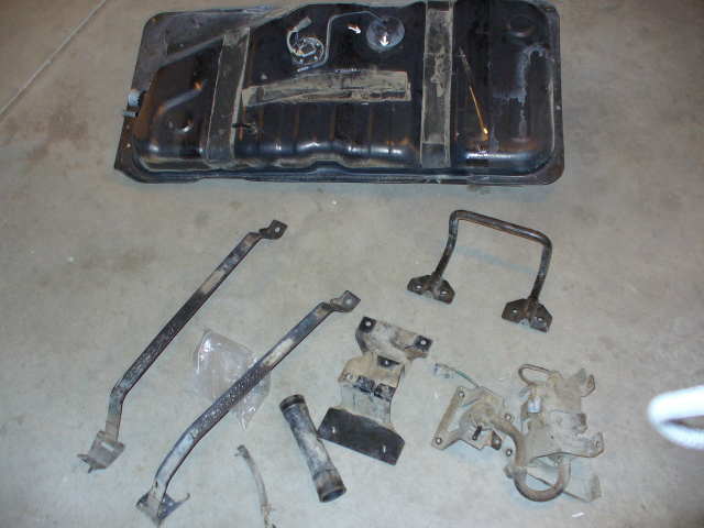
That forward hoop bracket looks to be ment to support the front of the spare tire so that it does not contact the fuel tank.
That forward hoop bracket looks to be ment to support the front of the spare tire so that it does not contact the fuel tank.
post #16 slacker

don't I get some prize for the correct guess?
don't I get some prize for the correct guess?
NO.
Thanks for asking.............


- Thread starter
- #25
I spent some time under the truck and I couldn't see the connector that mates up to the sub tank. There is another connector, but it has a bigger connector case and won't mate. Any one else have problems locating it?
The stock transfer pump assmbly is heavy. I found the screw holes with nuts that George shows in his rightup. I am thinking of removing it from the assembly bracket and butting a bracket on the pump and mounting it to the existing holes with captive nuts. Any comments about this thought would be appreciated.
There are two connectors here on the pump not obvious to me how they mate and to what. Any more guidance would be appreciated.
- Thread starter
- #26
I spent some time under the truck and I couldn't see the connector that mates up to the sub tank. There is another connector, but it has a bigger connector case and won't mate. Any one else have problems locating it?
The stock transfer pump assmbly is heavy. I found the screw holes with nuts that George shows in his rightup. I am thinking of removing it from the assembly bracket and butting a bracket on the pump and mounting it to the existing holes with captive nuts. Any comments about this thought would be appreciated.
There are two connectors here on the pump not obvious to me how they mate and to what. Any more guidance would be appreciated.
Bump
I spent some time under the truck and I couldn't see the connector that mates up to the sub tank. There is another connector, but it has a bigger connector case and won't mate. Any one else have problems locating it?
The stock transfer pump assmbly is heavy. I found the screw holes with nuts that George shows in his rightup. I am thinking of removing it from the assembly bracket and butting a bracket on the pump and mounting it to the existing holes with captive nuts. Any comments about this thought would be appreciated.
There are two connectors here on the pump not obvious to me how they mate and to what. Any more guidance would be appreciated.
Ken, I did what George did and didn't use the bits of harness found on the chassis. So not much help there I guess...
For mounting the pump assembly I pulled all of the carpet and exposed the floor, then mounted the pump on the existing holes and drilled the rest just like George again.
Not sure what you mean by the last bit about the pump connectors, is it the two in this pic? They just need the 12V supply from George's ecu

- Thread starter
- #29
Ken, I did what George did and didn't use the bits of harness found on the chassis. So not much help there I guess...
For mounting the pump assembly I pulled all of the carpet and exposed the floor, then mounted the pump on the existing holes and drilled the rest just like George again.
Not sure what you mean by the last bit about the pump connectors, is it the two in this pic? They just need the 12V supply from George's ecu
Thanks Mike, Thats helpful. I will see how much of my outback drawers I have to remove to get those bolts up.
I just wanted to find the connector so I could cut it off like George did.
I'll go spend some quality time in the garage. If I can't find it, I'll just snip off the connector and run wires directly.
I think I'll try and see about getting the pump in tonight and then work on the wiring before I do the filler neck and the tank. Hopefully I will have it done by Friday and then can focus on getting ready for Moab.
If nothing else, I'm a EE and have all the pinouts I need and can make my own hraness all the way back.
- Thread starter
- #30
According to Georges schematic, the signal Pump_Solenoid_+ve is connected to both the pump and solenoid, there are not two seperate signals, is that correct?
edit - I see why I don't think I am seeing the correct connector. There is suppose to be a small jumper harness that mates to the bigger spare connector. My subtank is missing it.
Georges Tank

My tank
edit - I see why I don't think I am seeing the correct connector. There is suppose to be a small jumper harness that mates to the bigger spare connector. My subtank is missing it.
Georges Tank
My tank
Last edited:
Ah, I see that now too. That would have been nicer to have versus that hoop! 
- Thread starter
- #32
So here is what I am thinking the schematic is. The area I am unsure of is the two connectors on the transfer pump. I am guessing on those, if someone has a diagram showing wire color codes, that would be great.
Edit - updated corrected wiring diagram

Edit - updated corrected wiring diagram
Last edited:
- Joined
- Mar 11, 2006
- Threads
- 207
- Messages
- 1,928
I spent some time under the truck and I couldn't see the connector that mates up to the sub tank. There is another connector, but it has a bigger connector case and won't mate. Any one else have problems locating it?
Did you drop the spare? Look for the where harness is grounded to the chassis. It is almost dead center. The grey plug will mate to the ABD harness you removed for you retro-locker install. I believe it is a 6 cavity with only 5 pins installed. As I said before the 3 yellow wires run all the way to the front of the vehicle and are unused, the brown on is a ground and goes directly to the chassis ground on the reat sill, the final one, don't remember the color but it is in my previous post runs up the rear DS pillar.
- Thread starter
- #34
Did you drop the spare? Look for the where harness is grounded to the chassis. It is almost dead center. The grey plug will mate to the ABD harness you removed for you retro-locker install. I believe it is a 6 cavity with only 5 pins installed. As I said before the 3 yellow wires run all the way to the front of the vehicle and are unused, the brown on is a ground and goes directly to the chassis ground on the reat sill, the final one, don't remember the color but it is in my previous post runs up the rear DS pillar.
As I posted above, I am missing the pigtail from the tank (3 pin) to the 6 pin cavity. That's why I didn't think it was there.
I am going to just build my own harness all the way back. Much easier than splicing in existing harnesses since the connectors don't mate anyways.
I am going to start a new thread on the wiring. I'll do an overall collection and write-up for the FAQ when I am all done.
- Joined
- Mar 11, 2006
- Threads
- 207
- Messages
- 1,928
Ok, I guess I don't understand your question. 3 wires come from the sending until, a ground, one to the gauge and one to the ECU. Toyota does not sell the mate for the plug on the factory sending unit, according to Dan they never did.
To make a harness to run from the sending take to the sill you will need the following
1 90980-11015 3 pin male housing
1 90980-11016 3 pin female housing
3 82998-12440 female pins
1 90980-10987 5 pin female housing
3 82998-12430 male pins
3 82998-12330 female pins
If you have done a rear locker retro fit you will have a harness with the last 2 items. You can splice 3 82998-12440 on to the ABS harness and add the 11016 you will have a sending unit harness that will connect the sending unit to the sill harness as mentioned above.
The sill harness and floor harness have the factory wires for the ecu connection, gauge an a 12v+. These run from the sill to the front most square plug in the drivers side kick panel. Use the 2 12330 to plug into the housing, I suggest adding a molex on the end first and you will have a harness that runs the length of the vehicle.
See post 11 for the housing in the kick panel.
https://forum.ih8mud.com/showthread.php?t=142077
Here is the informaiton on modifing the ABS harness
https://forum.ih8mud.com/showthread.php?t=140830
- Thread starter
- #36
I made my own harness per the electrical diagram Shown below. I did not want to use the factory wiring as it was easier to just build my own harness. I could check it and build it on a table and not have to figure out which wires to run and I do not have an extra locker harness sitting around. By the time I cut the old harness out of Sarahs truck and modified it, I was done. Plus I did not have the plug from the factory harness to the sub tank.

I used computer power connectors to run 3 wires to the sub tank and 2 wires to the Fuel assembly.
I ran the wires from the underside through the gromet shown in the picture.
I installed the transfer pump, harness and subtank.
Now all I have to do is connect the harness from the underside to the ECU harness I left by the kick panel, Install the dual filler and plumb everything.
I capped off the open plumbing with plastic tonight.
But there be a subtank there
Romer,
Your subtank installation is looking good. When you all said and done, can you please put this awesome mods on the FAQ. I bought a subtank from UAE and I too need some assistance/guidance on the installation. Thank you.
Your subtank installation is looking good. When you all said and done, can you please put this awesome mods on the FAQ. I bought a subtank from UAE and I too need some assistance/guidance on the installation. Thank you.
Ken,
Christo also said that I should get power from the battery to go to a 30 amp relay then to pump. The main power from George's should then go to the coil side of the pump relay? He said George's relay is not strong enough? I am not an electronic wiz so most of this is greek to me. I love the wench but not the soder gun.
Sorry to muddy up the water?
Last edited: