Steering knuckle centering

This site may earn a commission from merchant affiliate
links, including eBay, Amazon, Skimlinks, and others.

Joined
Oct 27, 2011
Threads
1
Messages
11
Location
Jeddah, Saudi Arabia
Dear gentlemen, your help is needed again please :) My question now is about front axle and front suspension and particularly steering knuckle and axle shaft. The manual says that I have to measure the difference between two lines that are scribed by the tools that are placed in the centers of the steeping knuckle and the axle shaft and then MINUS 3mm and as manual says that would give the thickness of the lower shim. What about if my distance is less then 3mm and actually was 2.65mm? If I would minus 3mm from that I would get a negative value (-0.35mm). I was trying to use some logic there but failed to do so as I could not see any reason why there is used 3mm and not another value? and why I have to minus those 3mm from the difference between two lines.
Thank you in advance. :cheers:
 
I haven't done this but will be next month, so I'm interested in your experience.
I would guess that there must be something wrong with your procedure. I would guess that either you are tightening the tool too much so that the bearing load is too much, or you aren't measuring the distance between the flat spots on the tool spacers under each nut, or possibly the bearings/races aren't installed correctly. Those are the things that I would check if I were doing the job and got the result that you did
 
I checked those measurements may be 6 or 7 times and every time I got the same results. There is nothing complicated there as long as you would tight the nuts with the correct load (apply a correct bearing preload). I even checked the bearing preload that was mentioned in a manual and everything seemed ok. It is very difficult to install the bearings in a wrong way as there is a fixed place for them and as well it is difficult to measure the distance between two flat surfaces by a caliper in a wrong way too. I checked and rechecked again and again, spend a good few nights thinking about the reason of those 3mm considering the gaps in the bearings, wheel load etc but could not come to a logical explanation of that equation. So at the end I just decided to follow just a common sense and some logic and put everything together. So far so good, but it would be interesting to see if some people came to some conclusions with this procedure. :cheers:
 
The 3 mm offset is a constant that must come from some offset that is inherent in the tool or in the knuckle-axle tube alignment. If you are getting negative values for the bottom shim, then there may be something wrong with the either the tool installation and use or the knuckle or axle tube are out of spec (bent or worn?). Are you getting negative values on both sides? If so, this would seem more likely a problem with the tool itself.

My experience is that reusing the same shims it originally came with works fine. The may issue with centering the axle is to prevent the seal from leaking. The Marlin seal is supposed to be more accomodating for axle centering error than the stock shim.
 
Yes, I got the same values on both sides that is why I am interesting in the reason of applying those 3mm. I looked at mechanical point f view on the centering tool as well as on axle shaft and steering knuckle in order to understand the procedure how it works but unfortunately could not find any explanation for those 3mm. :cheers:
 
when i did a knuckle upgrade i too was getting negative values . the error was coming from the use of the tool . it took me almost 10 tries before i figured it out . my error was comeing from the measurement you take when you put the tool in the spindle. the spindle bushing was worn and the tool was fitting too loose. the tool is really not all that accurate anyways . you need to make sure the piece fitting into the brass bushing is tight and that the scribing tip is also tight and square in the hole. the tip itself also can have some slop which will give a wrong reading . you need to hold everything tight in place when when scribing the line. at least this is what worked for me.

:meh:
 
So at the end I just decided to follow just a common sense and some logic and put everything together. So far so good, but it would be interesting to see if some people came to some conclusions with this procedure. :cheers:

I am coming up with your same problem and was wondering if you could explain this common sense you used a little more. Did you have front drum brakes? Did you use a kit from marlin crawler? My kit is from there and they use slightly different bearings than the stock ones.
 
My mind is a bit fuzzy bit I think there is a different tool for the drum brake vs. the disk brake knuckle. Are you using the right version tool for your knuckle?
 
I don't believe there are different tools for disk and drum brakes. I recently completed this procedure, on a mini truck disk conversion, using an older factory manual. at the end of the instructions, on reassembly, it states, "Adjust the brakes. Refer to Brake adjustment on page 7-5." This would infer that the procedure (tool) was for a drum brake setup. The install went well and the preload was perfect.
The manual also states,"Effecting the adjustments using the Steering Knuckle Centering Guage, premature wear of the axel inner shaft bushing and outer shaft bushing and abnormal vibrations produced wile making a sharp turn on a curve can be reduced to a great extent.". The point is, the reason for proper shim adjustment is not just wear on the axel seal and the resulting oil leak.
If you are geting a negative shim number, somethings bent, worn, not installed properly, or the tool isn't being used the correct way.
 
I am going to try it again tonight when I get home from work. After doing a little poking around late last night, I found that there was a little bit of play in both the pointer on the tool, and on the actual marking tool where it meets the inside of the axle. I am going to try holding all that stuff up to the most upright position (make the slack be on the bottom) and see if that changes the number.

Question: do the axle housings with the birfield have a bushing at the end of the axle housing? The manual shows one for the ball and claw style, but not for the birfield type. On mine, I don't see a bushing. It has something that looks similar to a bushing, but definately isn't brass. It looks like one piece too(part of the axle housing), not a seperate bushing.
 
I know this doesn't answer your question, but i'm sure it will be helpful for others reading this thread.

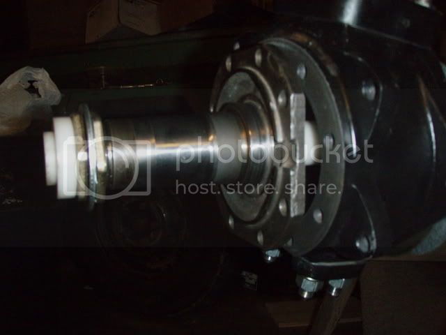
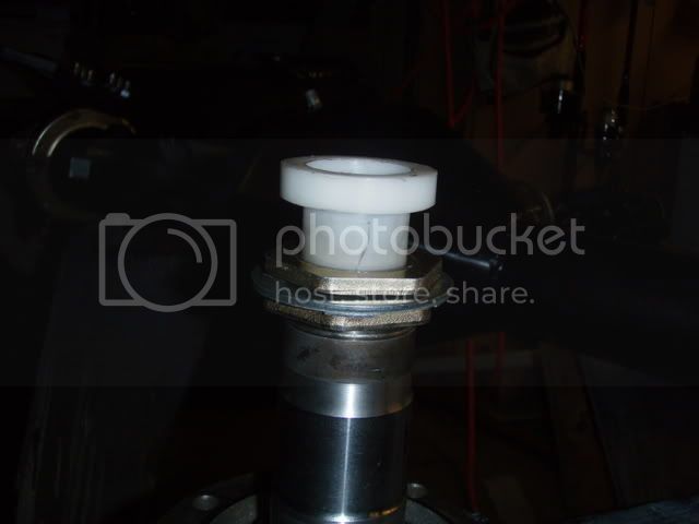
Everyone I know who has used one has been a bit confused. I never could buy a factory alignment tool so I made my own knuckle centering tool out of delrin.

I machined a piece of 1.5" solid rod to fit inside the spindle bronze bushing. Then I machined a spacer puck which fit inside the axle @ the axle seal (so remove the axle seal, insert this spacer... I want to say I made it to be about 2" long), and another spacer puck which fit the end of the spindle.

This allowed me to line everything up, then attempt to slide the spindle on the knuckle. If it bolted to the knuckle, it was aligned. If it didn't, I adjusted the shims until it bolted up.

I did this 3 years ago, and haven't had a problem.

P1170039.jpg

P1170036.jpg
 
I don't believe there are different tools for disk and drum brakes.


The scribe adapter piece that fits into the birfield seal area and the disc brake spindle bushing will not fit into a drum brake spindle bushing as the drum brake spindle bushing has a significantly smaller ID compared to a disc brake spindle bushing...


:meh:
 
I may haver an answer to the negative number mystery. I just got off the phone with a friend who encountered the same negative number problem.
Let's see if I can explain it. When using the steering knuckle centering guage make sure the knuckle is in the proper upright orientation. If you scribe a line on the gauge that is installed in the axle housing and then install the gauge in the (upside down) knuckle and scribe a line a negative number will result. This is easy to do if you are working on a bench away from the axle housing. What has hapened is that the gauge has efectively been flipped over when scribing the lines.
The 3mm has to do with the angle of inclination of the centering guage rod and the lines that are scribed around it in relation to the true center of the axle shaft.
Also my centering guage has an adapter that slips over the scribing (pointy part). That may account for different opening sizes?
 
So.....How do you do this on the drum brakes because as you said, the tool does not fit? I noticed in the FSM that it gives the part number 09634-60012 for the tool, but when I do a search at spx it only comes up with the 09634-60013 that is listed in all the threads.
Any help is appreciated.:)
The scribe adapter piece that fits into the birfield seal area and the disc brake spindle bushing will not fit into a drum brake spindle bushing as the drum brake spindle bushing has a significantly smaller ID compared to a disc brake spindle bushing...


:meh:
Thanks for the input. This helped me figure out what I was doing wrong. I sure hate realizing I am an idiot, but luckily you pointed it out, lol:doh:

I may haver an answer to the negative number mystery. I just got off the phone with a friend who encountered the same negative number problem.
Let's see if I can explain it. When using the steering knuckle centering guage make sure the knuckle is in the proper upright orientation. If you scribe a line on the gauge that is installed in the axle housing and then install the gauge in the (upside down) knuckle and scribe a line a negative number will result. This is easy to do if you are working on a bench away from the axle housing. What has hapened is that the gauge has efectively been flipped over when scribing the lines.
The 3mm has to do with the angle of inclination of the centering guage rod and the lines that are scribed around it in relation to the true center of the axle shaft.
Also my centering guage has an adapter that slips over the scribing (pointy part). That may account for different opening sizes?
 
So.....How do you do this on the drum brakes because as you said, the tool does not fit? I noticed in the FSM that it gives the part number 09634-60012 for the tool, but when I do a search at spx it only comes up with the 09634-60013 that is listed in all the threads.

The number on my tool from SPX is 09634-60014. The center sribe piece has a removable sleeve. I'm assuming that it fits both drum and disk axle housings.
 
In my case there was a sleeve to adapt to either the disk brake style axle or leave it out for the drum brake side in the centering tool.

The 3mm you've noted is the different in the size of the housing and the expected value of the tool from flange to flange when installed. This is factored in simply as an expected difference in size. They are not equal. When using the tool you are to determine the inconsisitancy to be fixed with slims including the amount to maintain preload. There removing the 3 mm just creates and equality. (The only other logical reason would be the angle of the scribe needing to be adjusted for but, in short that is the same thing. The housing tool marks will not scribe the same based on size/position based on it manufactured dimensions.)

With all this in mind you should not see negative values. If you do have negative values then check the bushings in the spindle housing. That is what the problem was for me... I changed the spindle bushing and and walla ... it was right. The measurements here are so close it really does matter. Also, based on what I have seen in experience the upper and lower shims will be pretty close to the same value. You can use that and an indicator to whether you are close or not.
 
knuckle centering tool

Where can you get one of these tools? I am quickly approaching a standstill on my front knuckle rebuild as I dont have one and cant find one :I
 
Back
Top Bottom