Short on my Engine Circuit - Help!

This site may earn a commission from merchant affiliate
links, including eBay, Amazon, Skimlinks, and others.

Honger

Joel, TLCA #21509
Supporting Vendor
GOLD Star
Joined
Aug 11, 2005
Threads
89
Messages
3,410
Location
Peoria, AZ
Okay, so I have a short on the "Engine" circuit in my 77.

According to @Coolerman's schematic for non-USA 40-series, that services the following items:
- Voltage Regulator
- Fuel Cut Solenoid
- VSV
- Computer T.P.
- Speed Sensor

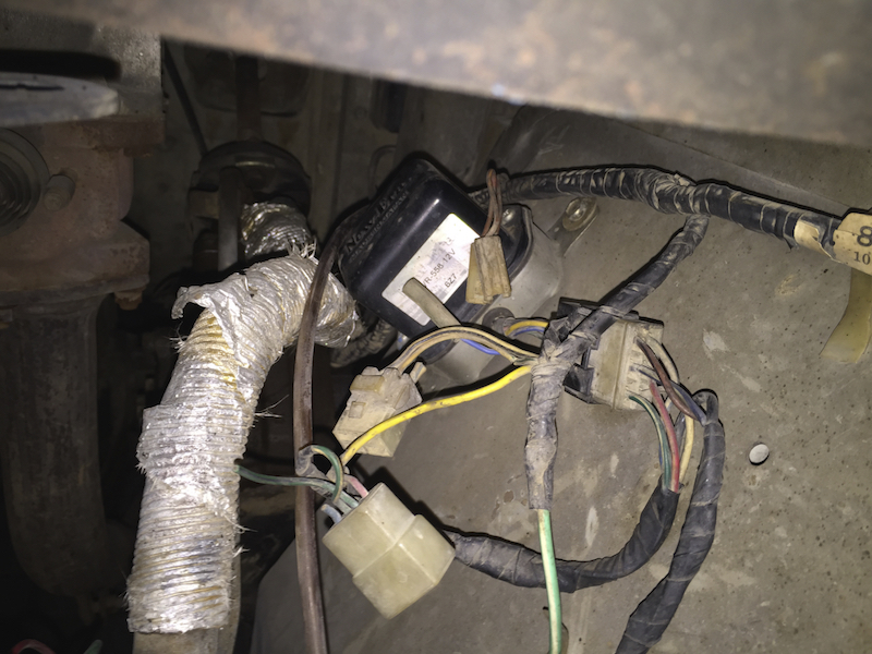
I'm pretty sure the short is somewhere in this rat's nest of wires...
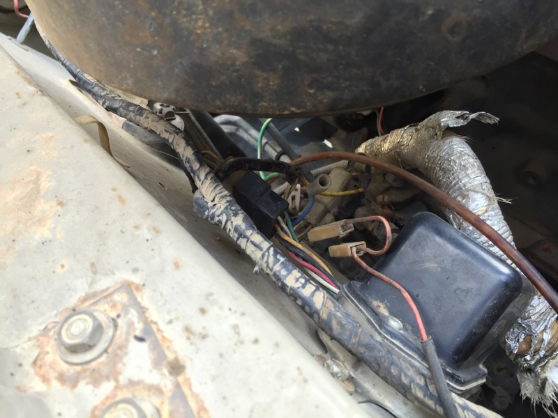
027wirenest.jpg


The shop who installed my power steering removed that whole fender for the work. It's quite likely they exposed something or shorted something that was already in a risky state.

I've got a stock voltage regulator sitting on the firewall (it's the 3-wire version, which matches the schematic from @Coolerman ).
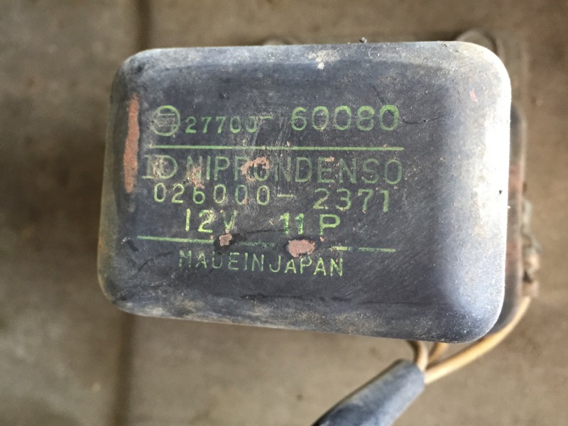
028stockregulator.jpg


But it doesn't appear to be completely connected...
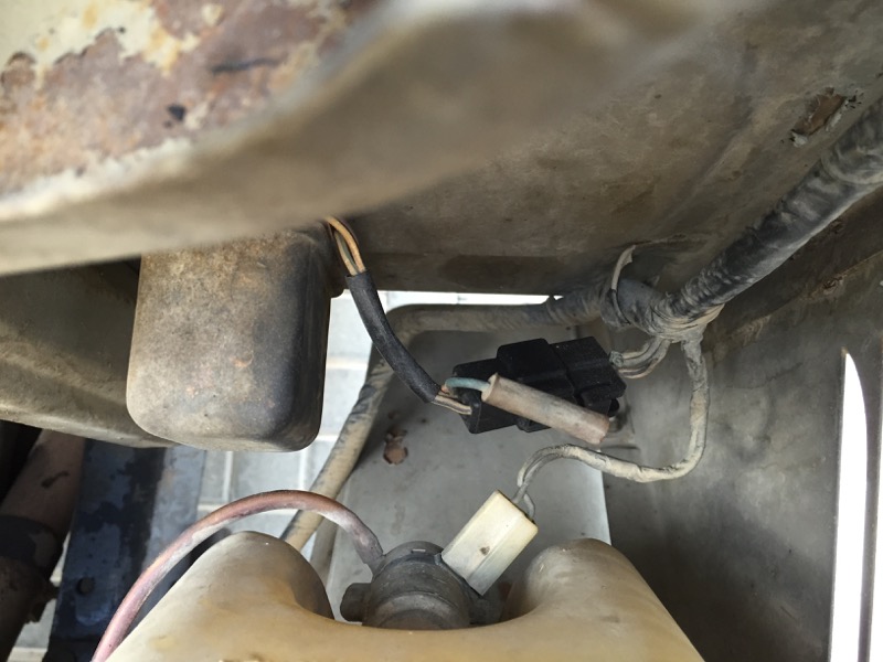
029stockregconnect.jpg


And I have an aftermarket regulator installed as well...
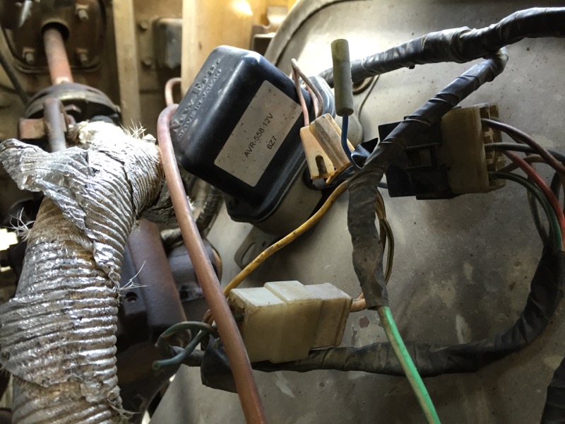
030otherregulator.jpg


That voltage regulator has six wires. It sits in the rat's nest with spliced in connectors and some unused connectors and some open cut wires. Yikes!

I'm not clear on where I find my VSV, Computer T.P., and Speed Sensor. Which brings me to my list of questions:

1. Do I have the VSV and Fuel Cut Solenoid correctly circled below?
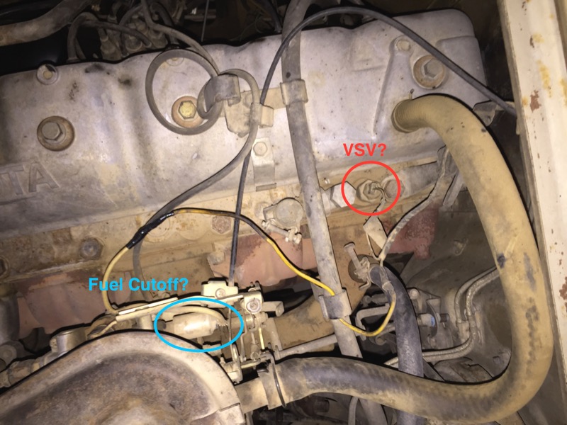
031vsvandfuelcutoff.jpg

2. Where do I find my Computer T.P. and what is it?
3. Where do I find my Speed Sensor and what is it?
4. Am I on the right track with finding my short? Any other pointers for me?
 
That VSV you have circled is the Temp sending unit. It is inserted into the head. A clue on finding VSV, Vacuum Switching valve, is vacuum requires hoses to function. There are no hoses on the temp unit.
 
Okay... temp sender and NOT my VSV, got it.

Any clues on where I find the VSV? I've looked and not finding something that appears to be one. Would help if I could find a pic of one... I've searched and not found a pic.
 
You could install a one-wire alternator and eliminate the voltage regulators completely. Simpler is usually better in my world.
 
Go to google and type "images: fj40 vsv" to see pics - in my US spec Fj40, it's on the driver's (right) fender

hth

Thanks for that... not sure why I didn't think of that. I had done a mud search but couldn't find a pic... Google gave me a pic which happened to be on mud.
https://forum.ih8mud.com/threads/vsv-part-for-78-fj40.226005/

I definitely don't have one of those. It seems this is part of Emissions Control Systems... and here in the Middle East I'm not surprised mine wouldn't include this. I'm assuming that means I don't have the computer and speed sensor as well.

You could install a one-wire alternator and eliminate the voltage regulators completely. Simpler is usually better in my world.

That is a thought. I found my way to Rudi's (@bj40green) Voltage Regulator thread and have educated myself a bit. An alternator with integrated regulator is less parts... though not necessarily simpler. I'm going to take the old stock regulator off the firewall and open it up, clean it, and test it. If it works I think I'm going to work to restore the factory wiring and ditch the aftermarket piece.

Going to spend some time with the multimeter tonight and see where I do and don't have continuity...
 
So, we have a '77 FJ40 in the UAE right?
I see the OEM 3 wire VR on the firewall and an aftermarket 6 wire VR. Obviously somebody has been busy over there.
The blue bullet connector that's hanging there is for a capacitor (aka condenser) which is missing but not needed at this point.
It's for filtering out the electrical noise from the VR for AM radio reception.
So, you say that a fuse blows, right? Which one, how many Amps and when does that happen?

Rudi
 
It's my "Engine" fuse... it's a 15 amp fuse.

It actually doesn't blow immediately. But once I turn on the ignition the fuse and the clips on the fuse box start heating up. If I drive it the fuse will blow within a minute or so. It may do that even if I don't drive it actually, I've not let it sit very long heating up since I realized I had the problem.
 
Disconnect the Voltage Regulator, turn the key to the "on" position and see what happens.
Which VR is connected, the OEM or the AVR558 ?

Rudi
 
Disconnect the Voltage Regulator, turn the key to the "on" position and see what happens.
Which VR is connected, the OEM or the AVR558 ?

Rudi

Thanks a bunch for this idea Rudi!
As I was thinking about this today at work I figured I'd get home, unplug the old one, and find everything sorted.

032stockunplug.jpg


Sadly, it was still shorting... a nice heating up at the fuse box.

I started digging around the harness for the 6-wire, aftermarket VR and it occurred to me that there were two plugs in this location. I unplugged the old Toyota plugs which had obviously been "cut out" of the harness a bit in lieu of the 6-wire connection. That fixed it.

033unplugged.jpg


When my shop put this fender back on the truck after the PS install they must have just indiscriminately plugged together all the plugs they saw. Understandable.

I need to get the multimeter out during daylight and get an understanding of just what wires they cut, spliced, and re-routed in order to hack in this 6-wire VR. My plan is to get a new Toyota VR re-arrange the wiring and restore the harness to original and then ditch the aftermarket VR.
 
I should have known better than to think it'd be that easy.

The plugs that were done wrong caused a short... and more than that I think they damaged my aftermarket voltage regulator. Could the short have also damaged my alternator?

To complicate matters, I don't have the original alternator in place for 1977.

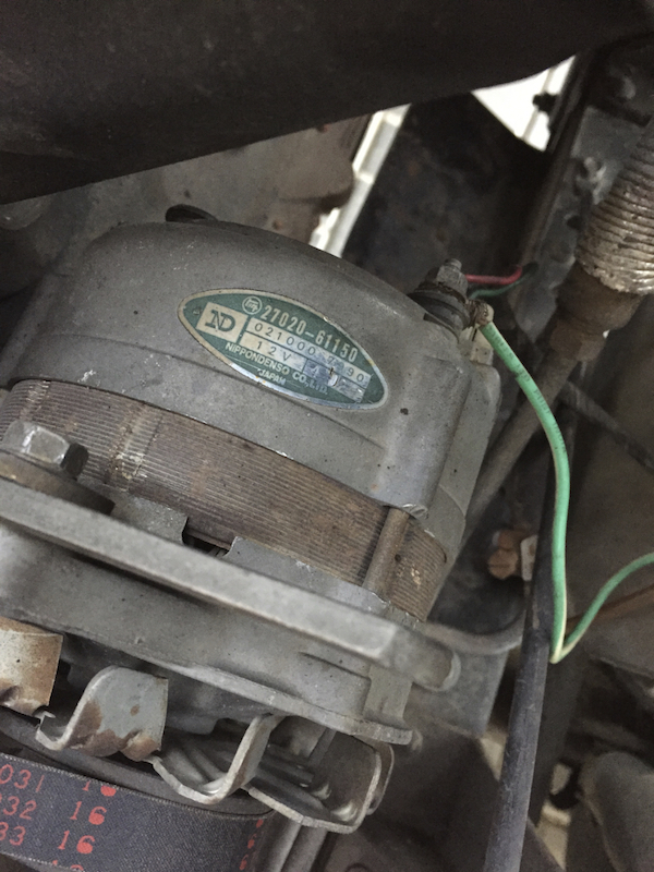
The alternator I have is as follows:
034alternator.jpg


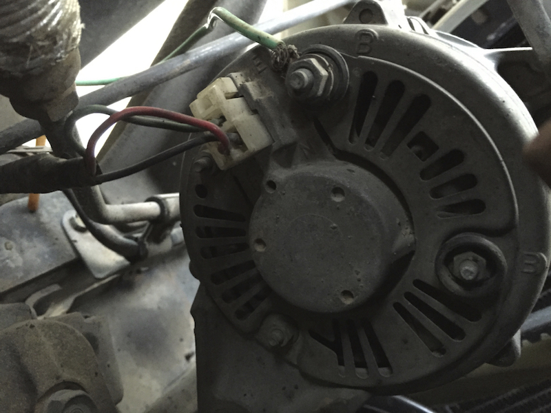
And the backside looks like so...
035altplugs.jpg


The factory VR that is on my firewall is 27700-60080. That's a 3-wire version, appropriate for the 1977 model year. That alternator that should go with that VR is 27020-60072, a 12V 40AMP unit.

My alternator is 27020-61150, also a 12V 40AMP unit, but from a later model Cruiser (80-87 40 and 60 series). The VR that goes with that mode alternator (per toyodiy) is 27700-15011, a 6-wire unit.

Since the alternator's have the same rating can I use either VR?

As I understanding it from @bj40green's VR thread, the extra wires are purely for the lamp to monitor charging, right? I don't have that lamp, so I don't think I need those extra wires.
 
Here we go......
Alternator 27020-61150 has a N terminal (bottom right) and that tells the 6 wire VR the charge status and from there the L (Lamp) on/off.
So if you don't use the N terminal you can use the 3 wire VR for this alternator.
E from Alt to E from VR
F from Alt to F from VR
N from Alt not connected.
IGN from VR to +12V switched from Ignition key.
Make sure that the VR makes good ground contact to the firewall.

Rudi
 
I see a big green, non factory, unsupported, with no terminal, B+ wire on the alternator also? That is a short waiting to happen also. My question: is where is the stock B+ wire and why did they not use it?

I'm assuming that green wire goes straight to the battery + terminal?
 
I see a big green, non factory, unsupported, with no terminal, B+ wire on the alternator also? That is a short waiting to happen also. My question: is where is the stock B+ wire and why did they not use it?

I'm assuming that green wire goes straight to the battery + terminal?

I think that that is part of the mess he's dealing with.

Rudi
 
I see a big green, non factory, unsupported, with no terminal, B+ wire on the alternator also? That is a short waiting to happen also. My question: is where is the stock B+ wire and why did they not use it?

I'm assuming that green wire goes straight to the battery + terminal?

Yeah... they come up with some "creative" solutions in the little mechanics shops here in the Middle East. Don't worry, I'm keeping the battery disconnected whenever I'm not working on the truck right now.

I'll have answers to your question shortly... I've just about figured out ALL of what they've done to the harness in this area.

I think that that is part of the mess he's dealing with.

Rudi

Mess is such a polite word.

More later...
 
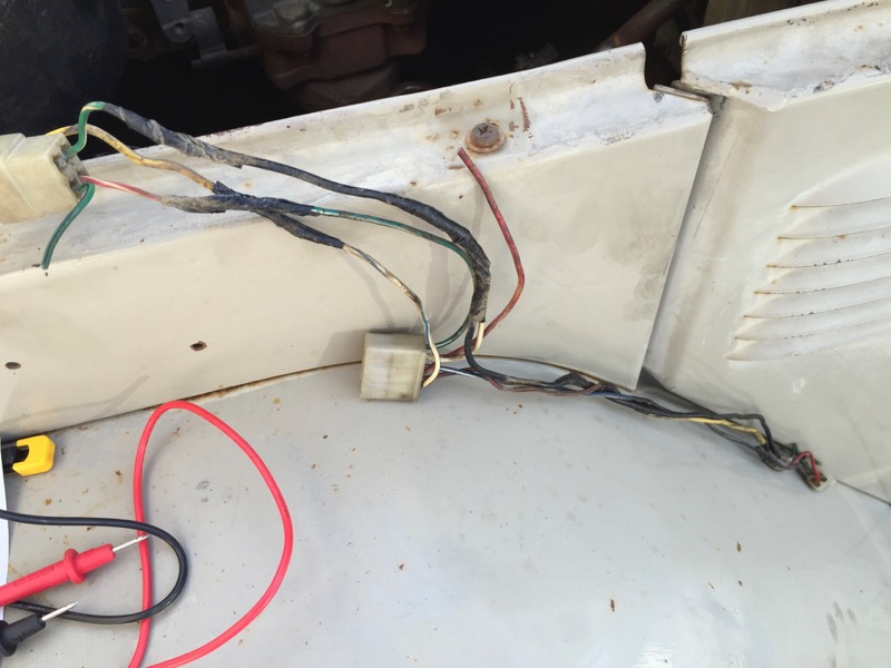
Okay... so here's a bit more detail. Spent quite awhile taking off electrical tape to get some transparency on the hack job wiring.

037harnesshack.jpg


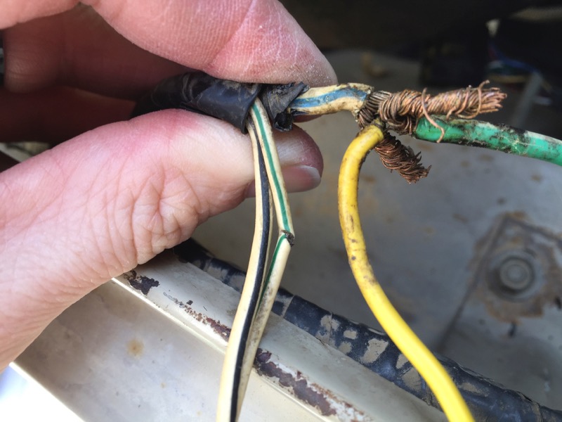
Found that the green wire from the B+ on the alternator was tied into the stock wire along with a yellow wire that runs to the new VR plug. You can also see a split in the "White w/ Green Stripe" wire which I thought was my culprit. I cut that, soldered it, and heat-shrinked it.
038spliced.jpg


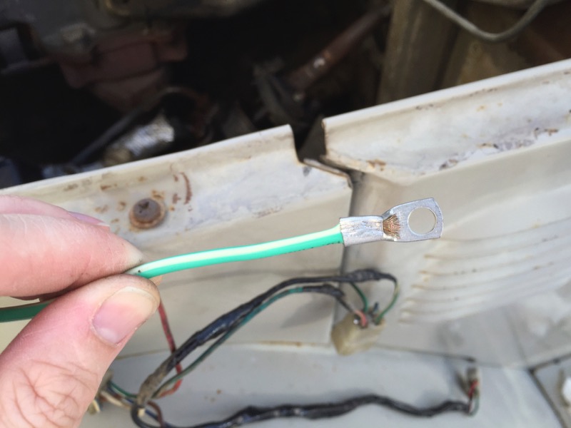
I went ahead and soldered that three way B+ splice. I also added a terminal.
039termination.jpg


Re-wrapped everything and gave it a test...
Alternator works.
VR seems to work... it's at least allowing the alternator to work.
Still heat build-up on the Engine fuse clips.
Ammeter still shows a nasty negative number.
I think I still have the short.

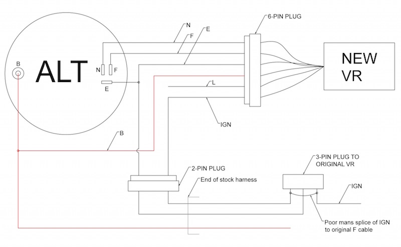
So here's the wiring diagram of the mess I've got. My CAD drawing makes it look much cleaner. And for clarity I didn't show the different splices and multiple colors of wires...

036wiring.jpg


Am I missing something?
Is the heat build-up on the Engine fuse clips normal?
Why the negative on my ammeter?
 
You say that heat is building up on the clips in the fuse box. Heat is a dead giveaway of high resistance - which you should NOT have at the fuse box. Are the connections tight? Are they corroded? Something is wrong at your fuse connections, if they are getting hot.

Take the fuses out and make sure the contacts are clean. Check the connections on the back side of the fuse box. Make sure the clips are tight against the fuses when the fuses are in.
 
Oh, and the negative on the ammeter just means you are using more current than your alternator is producing. Does it go away when you come above idle?
 
Your diagram is correct but the red B wire should be hooked up to the battery and not to the +B stud on the alternator.
You say: Alternator works. VR seems to work... it's at least allowing the alternator to work.
How do you know that? What is the voltage on the battery at idle and when you rev up to say 1000 rpm?

What does the Ammeter do with key in the "on" position (engine not running)? It should going a tiny bit negative because your ignition and gauge cluster are using a bit of current.
What does the Ammeter do with the engine running at idle?
What does the Ammeter do with the engine revved up?

FYI: E, F and IGN are the wires for the voltage regulator to work.
N, B and L are the wires for the "charge indicator light" (aka idiot light) circuit to work.

Rudi
 
Back
Top Bottom