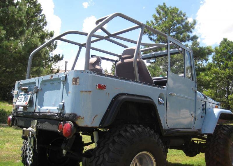
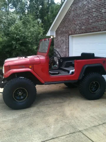
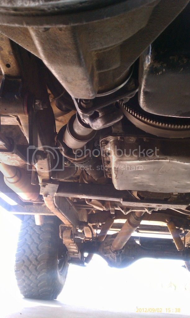
Not a 40 tech thing but a 55 thing!
Copy of a thread I put in 40 and 55 tech:
After running a rigged up and quite shoddy made (by me) drive shaft for 5 years or so I decided to have a Devin help me fix it properly. With the old carrier bearing setup I couldn't drive over 15 or so mph without some hellacious vibes. It worked great crawling around but at higher speeds it left a lot to be desired.
The reason we have to have a 2 piece shaft is because of running an 700R4 with a NP241 transfer case that is clocked flat. The shaft basically has to run around the transmission pan.
We decided to use a metal flange bearing with an id of 1 3/8". This should be beefy enough to handle the torque without being beaten up like the old carrier bearing setup. The biggest issue with using the flange bearing was being able to unbolt the shaft in case it had to be removed. To facilitate this we needed a flange that had a bearing surface on it that would also fit out t case side drive shaft.
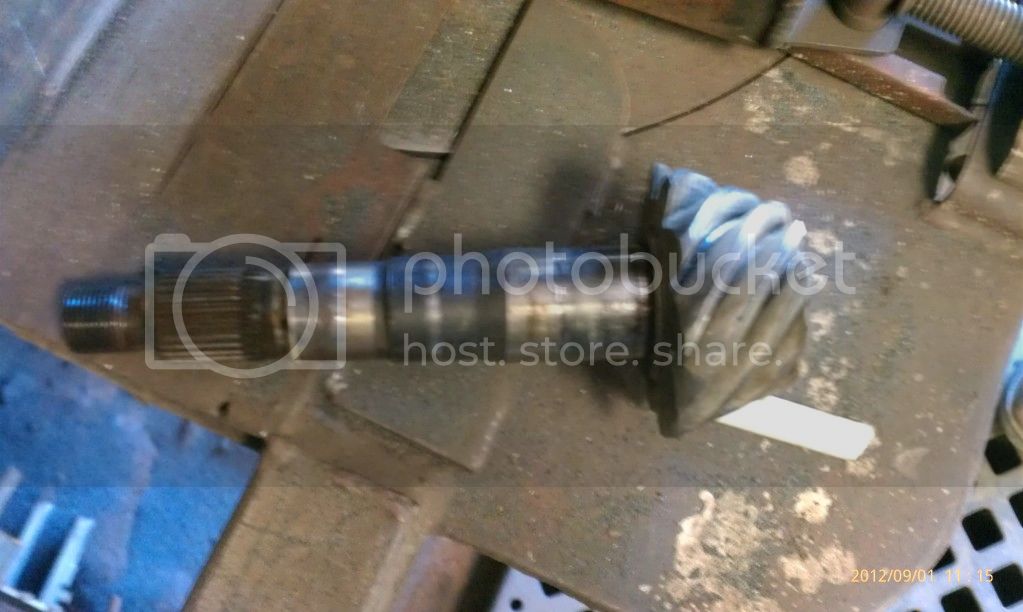
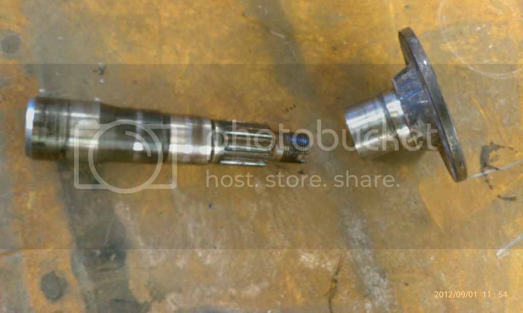
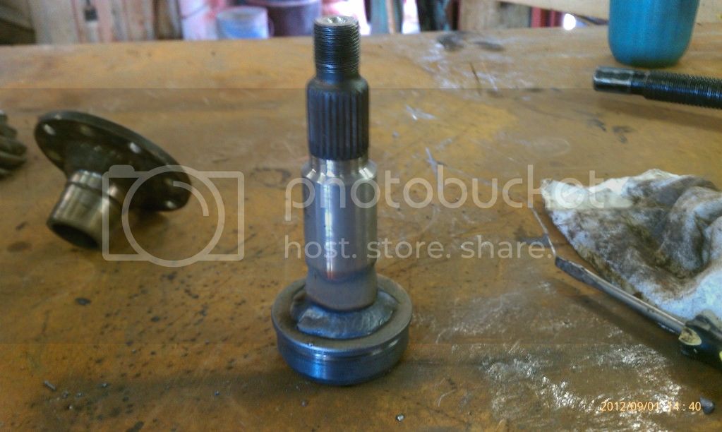
Looking around the shop we found this:
A pinion shaft from a mini truck differential. It would allow us to bolt a cv shaft from a mini truck to the t case side drive shaft and easily bolt to the cv shaft.
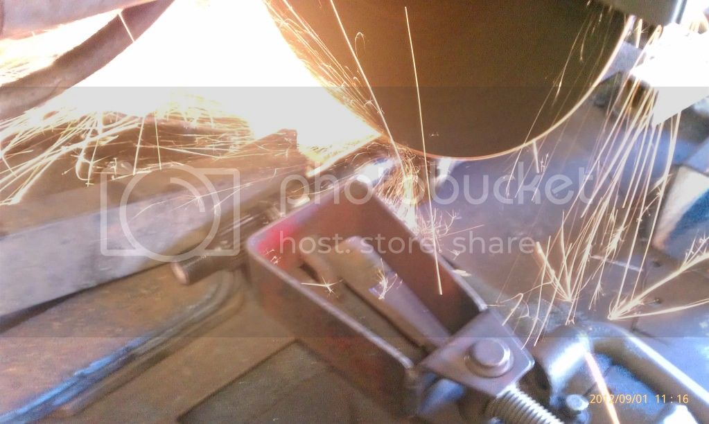
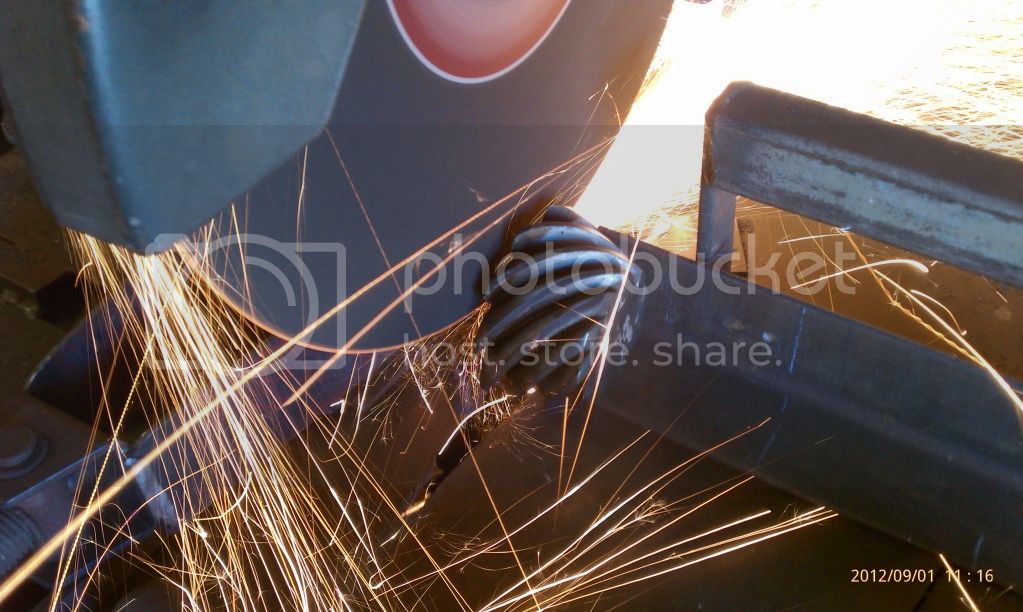
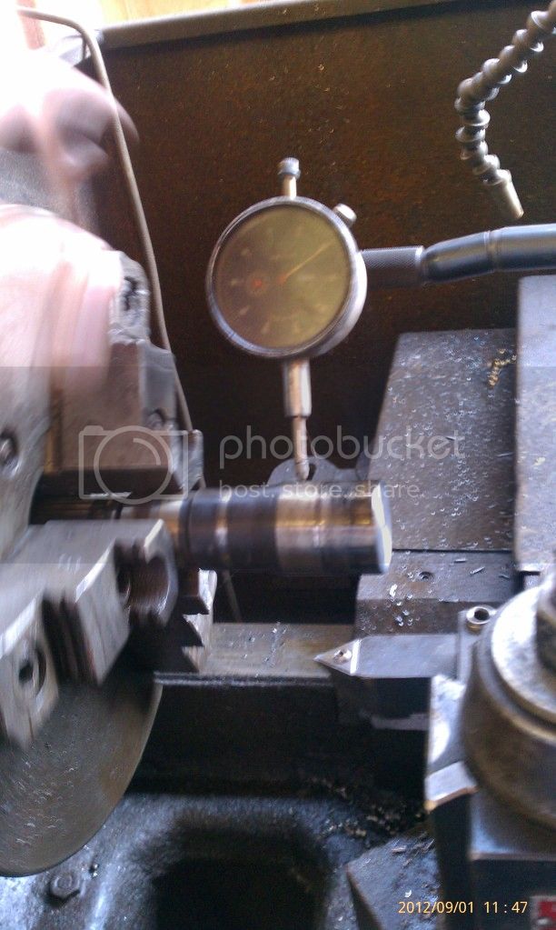
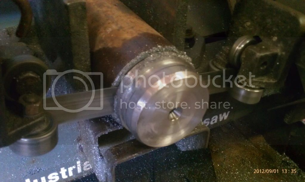
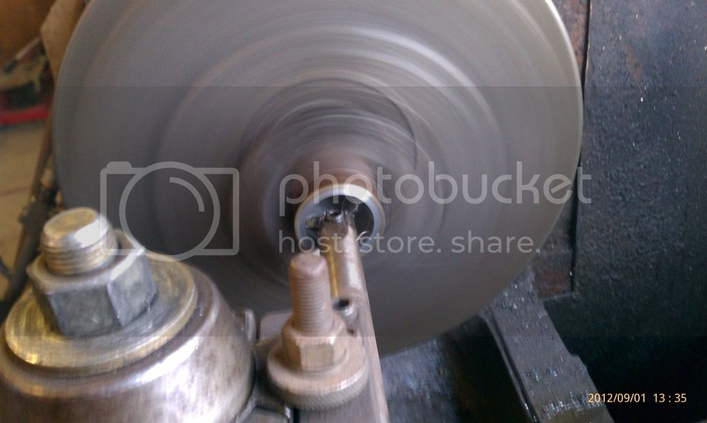
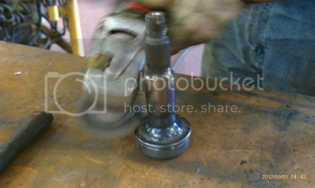
First we cut off the head of the pinion and then chucked it up in the lathe to true the end up.
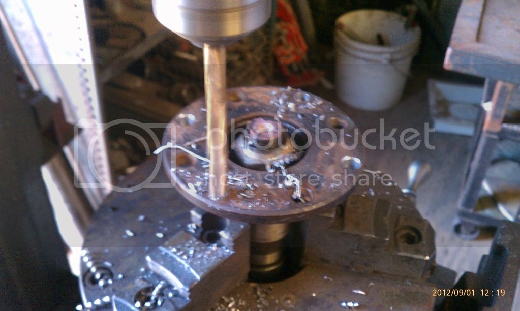
Next we re-drilled the pinion flange so that it would mate up to the cv shaft. Having the turret jaws for the milling machine came in real handy.
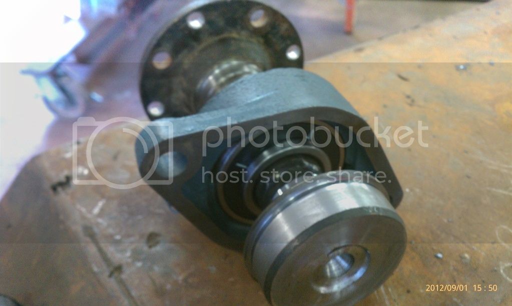
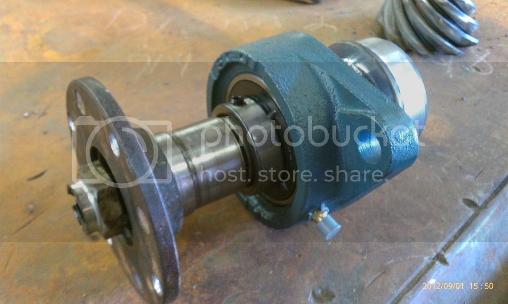
Then we made some bushings to make the flange shaft bearing surface match up with the id of the flange bearing and the busing to mount up into the t case side shaft.
Next the bushings were both welded onto the pinion shaft, indexed and turned down to the proper sizes.
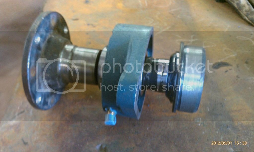
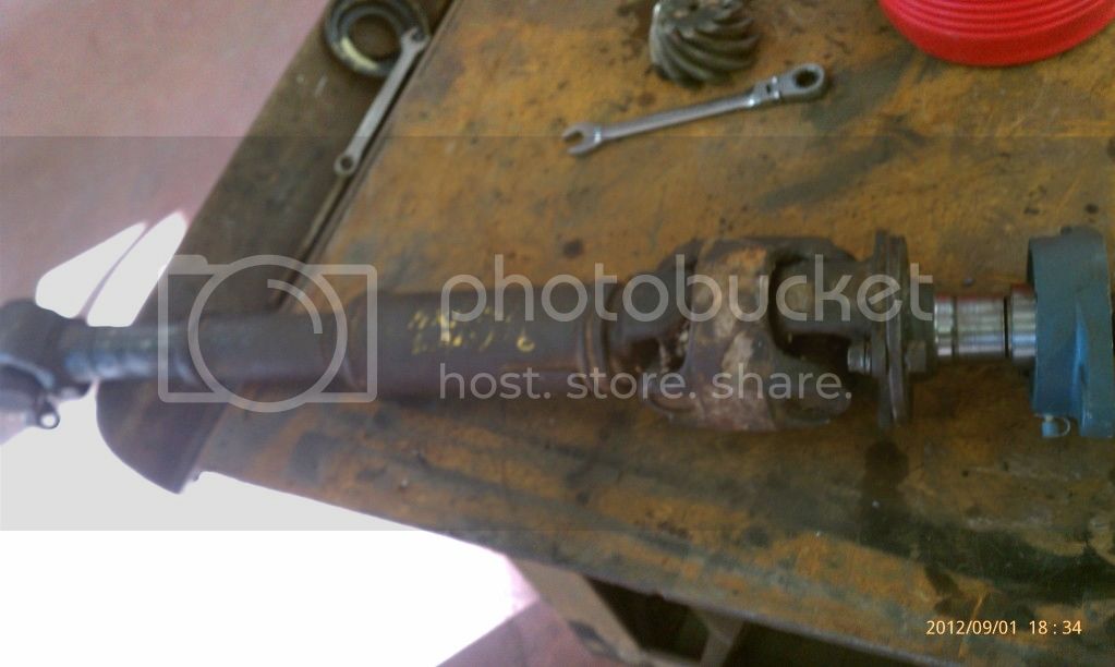
The flange was then test fitted to the pinion shaft.
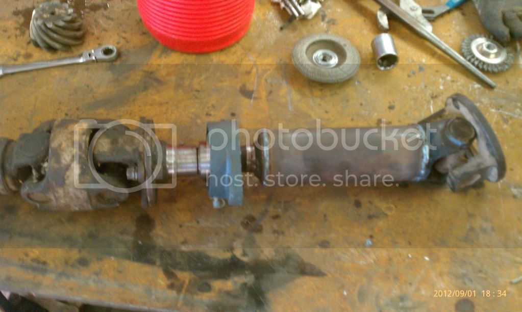
The t case side shaft was cut to length and the altered pinion shaft was welded to it.
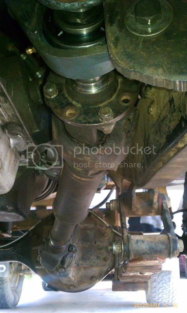
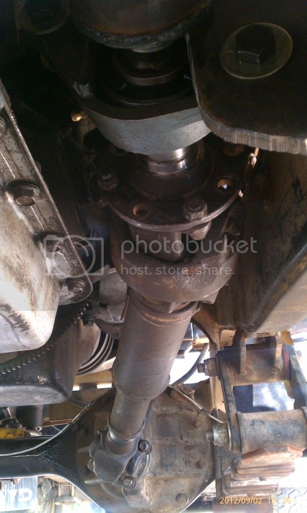
It was all assembled and bolted up.
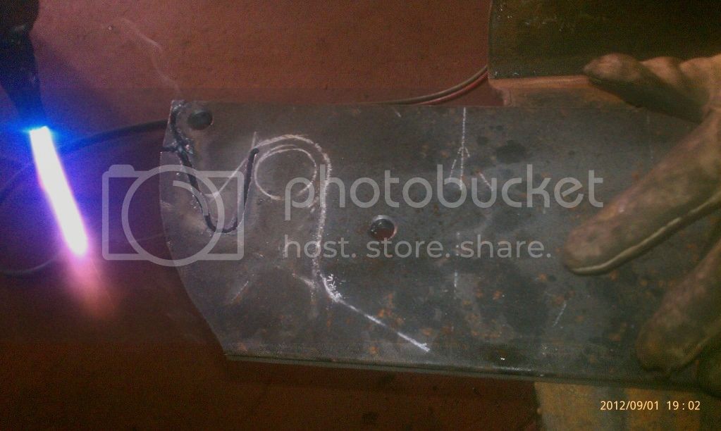
Then we made the 1/2" plate to mount the flange to the frame beside the transmission.
We then welded the plate into place and bolted it all up solid.
With this setup we were able to drive up to 50 mph without any major vibes. The cv joint should really help soak up the vibes and help offset the angles. Time will tell how long and how well it stands up to the small block 400 but it will definitely be better than the old setup and I still have my flat belly on the Pig.