
Glow plug relay keeps clicking

This site may earn a commission from merchant affiliate
links, including eBay, Amazon, Skimlinks, and others.

Joined
Feb 22, 2015
Threads
3
Messages
19
I am rebuilding a 1983 Bj42. The actual status is a chassis, with four wheels and a running motor.

Now, I have a problem with the no 1 glow plug relay. My car has got a Super Glow system.

When I turn the starter switch to the ON position, both glow plug relays are clicking on. During a few seconds, glow plug relay no 1 keeps clicking like a machine gun. Glow plug relay no 2 clicks off after a while.

I did some tests with a cold engine (6 degrees Celcius):
- Temperature sensor disconnected -> glow plug no 1 keeps clicking during 11 seconds, glow plug no 2 clicks off after 30 seconds.
- Temperature sensor connected (and a few minutes cooling down) > glow plug no 1 keeps clicking during 11 seconds, glow plug no 2 clicks off after 23 seconds.

Has anybody a clue why the glow plug relay keeps clicking?

Thanks,

Arjen
 
Measure the input voltage to the coil of the relay, and the resistance to ground on the ground wire for the relay coil. If the relay is chattering it can be because there is insufficient power to maintain the coil pull....
 
A ground wire directly to the battery did not help.

I have measered the input voltage to the coil of the relay. It's about 4 V. On the relay, there is a 24V label, so I think it should be 24 V? If so, why is it 4V?

The voltage on pin 2 (=wire to the relay) of the timer is also 4V. The click sounds very powerful.
 
If you have a damaged wire, or bad connection that can cause a voltage drop. If you are losing 20V that would be cause for a relay to chatter. Sounds like the output of the timer is not providing what it should, is the input voltage of the timer good? If so, I think you have narrowed it down to the timer. It is possible that a very dirty contact inside the timer can cause a voltage drop, so if you can get it apart (I've never tried) you may be able to clean up the dirty contact at get it back to an acceptable output voltage.

Perhaps @bj40green has some better insight?
 
Try this in the 24V and Diesel forum. There probably will be someone there that knows the glow plug system real well.

Don
 
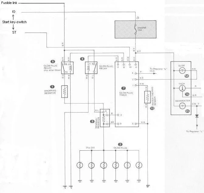
glow Relay No.1 gets his power from pin1 Pre Heating Timer.
Relay No. 2 gets his power from pin5 Pre Heating Timer.
Check the voltage on pin 1 and 5. If pin 11 and 4 are OK but pin 1 and/or pin5 are too low, the problem is in the Pre Heating Timer box.
Open the box and take (close up) pictures from both sides (components side and print lay out side) and post here.

9 wire super glow RM132E_1-crop.webp


Rudi
 
My wiring diagram is a something different.
I have measured the voltages:
2 = 4.5 V
6 = 22 V
8 = 22,3 V
10 = 0 V

The pictures of the timer:

Components side looks OK.
Print layout side looks a bit rusty.
 
I have measured the voltages:
2 = 4.5 V
6 = 22 V
8 = 22,3 V
10 = 0 V

2 = not good
6 = good
8 = good
10 = is only 22V when key is in start position

Check your board for bad soldering points. I've marked 2 of them but probably there are more.
That "rusty look" is a protective coating which colored brownish over the years.
Arjen_Pre heating timer_2_edit.webp


Here are some examples of bad/dry joints. Look for these.
bad solder1.webp
bad solder2.webp
bad solder3.webp
bad solder4.webp


Rudi
 
Hoi Arjen, sounds Dutch to me.

I have checked all soldering points. They all look fine.

Look fine or are fine? They don't look fine to me.

If they are OK then the bottom power transistor has to be checked.
The top transistor (bce) is the output for pin 8 which is relay 2
The bottom transistor (bce) is the output for pin 2 which is relay 1.
I have no idea about your electrical skills but the bottom transistor has to be checked.

ont3_pin numbers.webp


Rudi
 
Last edited:
I would try as Rudi suggested, though they may look good, it doesn't take much to cause a voltage drop.

Also check here and whatever is on the opposite side from here, looks like there is some corrosion on the board;
image.webp


And verify that these two points are not touching??
image.webp
 
I am indeed dutch.

I have found a colleague with more electrical skills, who thinks he can repair it. Hopefully next week.

To be continued.....


Arjen
 
It's a long time ago, but my colleague was not able to fix it. In the meantime I have found an other pre heating timer. The original timer has partno 28521-57010. The new timer has partno 28521-57051. The connectors are different. The Original timer has a connector of the lower picture, the new timer has a connector of the upper picture.

Connectors.webp


Can I replace the old timer by the new one by changing the connector of the wiring harness? Or are there more differences?

Arjen
 
Last edited:
In which manual did you find this?
The upper one has more pins than the lower one. There is a reason for that.

Rudi
 
Back
Top Bottom