Project Stitch: FJ40 2UZ swap, link, stretch

This site may earn a commission from merchant affiliate
links, including eBay, Amazon, Skimlinks, and others.

Joined
Feb 3, 2004
Threads
20
Messages
916
Location
Colorado
I wanted to start this thread to document my FJ40 build and some of the technical details I have been working through specifically related to adapting the A750 to the split case. There are now several successful 2UZ/1UZ swaps that have been completed but I am not aware of any that are using the split case.

Build Plan

  • 1979 FJ40
  • 2UZ-FE 4.7L V8 (06 4runner, VVTI), A750 5 speed automatic
  • Split case transfer case with 4:1 gears
  • FJ80/ 9.5 hybrid front axle, FZJ80 FF rear axle
  • FJ60 steering box, hydro assist (RHD steering arm, Y-link, 1 ton TREs)
  • 3 link front with coilovers, 4 link rear with coils
  • Stretch cab and frame (15-18” stretch, 108-110” WB)
  • 40” tires


Background

My dad bought this FJ40 in 1997 when I was a freshman in high school. It was a father/ son project and we spent a lot of time fixing rust damage, repainted it, and it was my daily driver through high school and most of college. I did some minor modifications to it over the years including lift springs and shackles, Saginaw power steering, header and exhaust, and swapped in a H42 and split case from an 82 FJ60. I always had plans for additional modifications to it, the plans evolved over the years but revolved around adding more power, bigger tires, better suspension, more stability (width), etc. I always struggled to find the money and time as I was building a career and raising a family so I slowly gathered parts and the cruiser basically sat in my shop gathering dust. Last year I came across a wrecked 2006 4runner and decided to buy it which finalized the plan for the drivetrain.

Image (4).webp


Image (5).webp


Stability as an objective of the build lead me to needing wider axles and an extended wheelbase. I picked up the 80 series axles a while back, the rear will probably get upgraded shafts, locker and gears (probably ARB & 4.88 but TBD) while the front is a hybrid build with 80 knuckles on a SF 80 rear housing, the short side inner axle shaft is longer than stock so I should end up around 67” WMS. I decided not to mess with leaf springs and go straight to linked suspension, the plan for the wheelbase is to move the front axle forward 2-3” and get the rest of the stretch in the rear. Along with the mechanicals of the build I am planning on new seats, roll cage, adding AC, and a FJ60 tilt steering column. I am trying to keep this as Toyota as possible which is why I have chosen some of the components that I have.

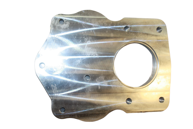
Image (3).webp
 
First steps were to pull the drivetrain, wiring harness, ECU, etc from the 4runner and the transmission and transfer case from the FJ40 to start figuring out adapters.

IMG_4603.webp


The A750 came in multiple Toyota vehicles:

  • The Tacoma & FJ Cruiser (1GR V6), 4Runner (1GR or 2UZ V8), GX470, Sequoia and Tundra (2UZ V8) with the VF4 transfer case. This version of the A750 has a short 23 spline output shaft.
  • The 100 Series Land Cruiser and LX470 with the 2UZ V8 and HF2A transfer case, this version has a long 19 spline output
Finding a complete 100 series donor would make this swap easier, the HF2A transfer case could be utilized and no adapters would be needed. The reasons I didn’t:

  • Availability and cost
  • The HF2A is a AWD case and needs modified for part time 4wd operation
  • The lowest gears available for the HF2A are 3:1
  • Because I wanted to
Adapting the split case to the A750 with the 23 spline output requires a solution for the output/ spud shaft and a solution for bolting the transfer case to the transmission case.

Starting with the spud shaft I discovered that Toyota makes an input shaft for the split case that has a 23 spline female input (36211-60090), it’s from a 79 series that runs a split case behind a R series transmission. There’s a couple things to sort out with that approach:

  • The transfer case input bearing needs to be swapped for a sealed bearing. The stock bearing is oiled by the transmission since it’s on the transmission side of the input seal, but the tail housing of the A750 is dry. It’s a 6307 bearing with an external snap ring
  • The transmission output seal needs to seal on the t-case input shaft.
IMG_4589.webp


The female portion of the split case input shaft is the same length as the input shaft of the VF4.

IMG_4584.webp


The length of the male portion, if you account for the thickness of the bearing, means the input bearing sits in the pocket in the front plate of the transfer case housing instead of in the transmission like it does with the H42, and the spacer between the bearing and the input gear gets eliminated.

IMG_4684.webp


IMG_4689.webp


Now having this info regarding the spud shaft this informs me that since the bearing sits flush in the transfer case housing and the bearing sits against the shoulder of the spud shaft, the shoulder of the spud shaft basically sits at the same plane as the front face of the transfer case housing. Since the female portion of the spud shaft matches the projection distance of the input shaft of the VF2 the front face of the split case transfer case would be at the same plane as the rear face of the stock A750 extension housing. In other words that is a complicated way of saying there is no room for a plate adapter between the extension housing and the split case, running a plate adapter was my original plan.


Moving on to plan B
 
Last edited:
Potential solutions:

1. Toyota makes an alternate spud shaft for this model that has male splines on the input:

IMG_0254.webp


It gets run with this coupler, likely Toyota revised this part to get rid of the splined interface, I assume the two mated together are the same length as the spud shaft I already have

IMG_0257.webp


2. Remove the extension housing and adapt straight to the back of the A750

IMG_4695.webp


Aside from it having the fill plug for the transmission it’s not that complicated. It’s a simpler and symmetrical bolt pattern compared to the t-case flange.

IMG_4697.webp


IMG_4698.webp


Time to start figuring out adapters
 
I knew that no products would be available for the transmission side of this adapter but there are several adapter plates on the market for the transfer case side. I checked out options on advance adapters website and narrowed it down to a couple options. The overall thickness I have to play with is somewhere between 5-5.25”

I see two options from the AA catalog, both would start with this plate that gets bolted to the transfer case:


Behind that option 1 is the t-18 to land cruiser adapter, per the cut sheet these two combine to 1.5” thick:


Option 2 is the 4l80 adapter, per the cut sheet these two combine to 3.19” thick:


I’m leaning towards the 4l80 adapter because there’s less thickness to make up, it has flanges to bolt through (so it can bolt to the transfer case plate and the transmission plate and the hardware isn’t trapped) and it has provisions for a crossmember mount. So basically I would need to make up 2” thickness.


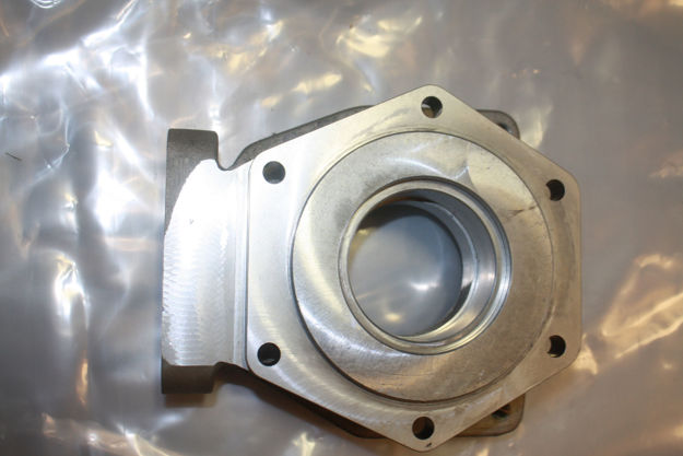
I went ahead and measured and drew up the adapter plate for the transmission and I’m got it test cut out of 1/8”. This fits over the raised circle on the back of the transmission and has provisions for fluid to drain.

IMG_0262.webp
 
That there’s a lot of figurin’!
Subscribed for sure!
Sounds like your in the groove of figuring it out, good luck.
 
Thanks, I’m playing catch up here for progress made over several months.

The test piece for the A750 adapter plate:
IMG_4731.webp


The holes in the outer wings need to be adjusted. I assumed the bolt pattern was symmetrical and averaged out the measurements between the two sides, that assumption was wrong. I don’t know if this is manufacturing tolerance or intentional but regardless, that’s why I did a $30 test piece instead of the final aluminum.

IMG_4732.webp


Another snag I ran into when dry assembling everything for the mockup- the spud shaft I bought appears to be out of spec. The bearing that installs on this shaft has a 35mm id and the shaft is larger than 35mm where the bearing seats. There are 2 steps where the shaft gets slightly larger as you go down for the input gear and bearing surfaces. I assume these are intentional and all the ODs are slightly too large. Unfortunate thing is I bought this from partsouq too long ago to exchange it.

IMG_4707.webp


IMG_4721.webp


IMG_4720.webp


Luckily I was able to press it back off with a bearing splitter and no damage is done, but when I got the bearing almost seated the race swelled enough that the bearing wouldn’t rotate.

For reference, the sealed bearing I am using: 6307 size bearing with an external snap ring, NSK TM307A1A10NR Manual Transmission Input Shaft Bearing.
 
I finalized the decision to run the AA 4L80 to split case adapter plate and got those two pieces ordered. Not much to look at but I was able to measure the hole spacing to start drawing the next layer of the adapter plates.

IMG_4750.webp


The 4L80 pattern isn’t symmetrical contrary to what I had previously assumed. I got it drawn up and cut a test piece along with rev1 of the transmission adapter:

IMG_4793.webp


I adjusted the holes at the bottom wings, trimmed the bottom edge slightly to clear the transmission oil pan, and made the top oil drain slot slightly wider:

IMG_4794.webp


The adapter ring for the 4L80 side needed one hole adjusted, the ID slightly larger, and the OD .25” smaller to not overhang the 4L80 adapter:

IMG_4799.webp


Here are the two overlaid to give an idea of how this will look

IMG_4812.webp


Let me say that Send Cut Send is awesome and an absolute game changer for building stuff like this with precision. If you are able to draw something in CAD it opens up a bunch of options for custom parts.
 
In order to finalize the adapter plates I need to get the spud shaft mocked up with the input bearing installed, and installed into the transfer case housing with the AA adapter attached. That will tell me the remaining thickness I have to make up.

I devised a redneck engineer solution to machining the spud shaft down to the correct diameter. An Amazon mini 3 jaw chuck with a Morse taper adapter that fits my drill press. This holds the shaft and spins it while I slowly grind the shaft to the correct diameter with a belt file.

Getting the shaft indicated in/ concentric:
IMG_4813.webp

OD before:
IMG_4814.webp

After about 30 min of slowly grinding and measuring:
IMG_4815.webp

IMG_4817.webp
 
This is a different way to go about it. Sounds like an awesome build. I will follow along.
 
The female part of the spud shaft had the splines recessed in a bit and the ID of the shaft was bottoming out on the transmission output shaft before it would fully seat. I went ahead and trimmed 3/16” from the end of the shaft and chamfered it.

IMG_4818.webp


IMG_4819.webp


IMG_4820.webp


Now the splines fully engage
IMG_4822.webp
 
And finally get the final measurement for the plate adapters.

IMG_4831.webp


IMG_4832.webp


IMG_4833.webp


1 7/8” which is perfect because the thicknesses of 6061 aluminum plate that Send Cut Send offers are in 1/8” increments up to 3/4”

I jumped the gun a bit and went ahead and ordered the first two adapter plates, the first being the plate that bolts to the back of the A750 which I had test cut, the final version is 3/8” 6061. This plate seals off the back of the transmission and sets the next adapter at the correct distance to clear the raised circle on the back of the transmission casting:
IMG_0271.webp


The next plate does all the work, it adapts the bolt pattern of the transmission (minus the two wing bolts) to the 6 bolt 4L80 pattern. The 4 transmission bolts in the center are countersunk so the next plate can sit flush. The 6 bolt 4L80 pattern is threaded for M10x1.5 studs and there are two sets of holes for stock and 11 degree clocking. This piece is 3/4” 6061 aluminum.
IMG_0270.webp


The final plate is a ring with the 6 bolt pattern that is 3/4” thick, I’ll be ordering it tomorrow.
 
Last edited:
I’m stoked to see you writing this up. I have a rolling dumpster fire fj45 chasis and a split case. My hope is to do the same axle set up. Your plan has a lot of similarities and I love that you’re sharing your approach.

I’m interested to see the final length. I was, mildly, considering the NWFab box as an adapter, but I am leery of the added complexity. The other issue is length. If your solution comes in shorter I’d likely drop the NWFab box off the list.

I have 4:1 in my current Tcase and it’s plenty for my needs. With an (Toyota) auto and a V8 the next rig should be perfect. Bonus points for limiting the non Toyota parts.
 
Interesting approach on the adapter. Following.

FYI, I realize you're past the development stage on your laser cuts, but SCS offers chipboard or hardboard laser cut which is far less expensive than having steel cut out for prototypes.
 
Made some progress over the weekend. The aluminum adapters came in from send cut send and everything fits. I had to address a couple items before dry fitting everything together.

The input bearing is retained by a snap ring and by the transfer case housing from moving toward the transfer case but there was nothing to stop it from moving toward the transmission. It was a pretty good fit onto the transmission output shaft but I dont want to rely on that splined interface and risk it getting sloppy over time. I had some rings cut to push against the other side of the snap ring and against the AA plate adapter.

The snap ring not seated below to illustrate the issue.
IMG_4865.webp


The rings. These are .074 mild steel and the darker rings are .015 spring steel. I used the larger spring steel ring to make sure the fit was tight enough.
IMG_4864.webp

The smaller ring installed against the snap ring. The larger rings sit on top in the larger diameter recess.
IMG_4866.webp


With that solved the countersunk holes in the intermediate adapter were too small. I assumed the countersink would be sized based on the size of the hole but it appears that when you select the countersink option it resizes the hole (or maybe I just ordered it wrong). Regardless an easy fix with the correct size drill bit and 7/8” countersink bit.

IMG_4849.webp

IMG_4850.webp

I also chased the threaded holes, they had a decent amount of metal dust in them.
 
With that I bolted everything up starting with the 3/8 plate on the transmission:
IMG_4845.webp

Then the intermediate plate:
IMG_4852.webp

Install the M10x1.5 studs (which needed to be shortened about 1/4”)
IMG_4853.webp

And the 3/4” spacer
IMG_4854.webp

Finally bolted up the front half of the transfer case and input shaft
IMG_4855.webp
 
I went ahead and shortened the studs and bolted the rear half of the case and output shaft on. Since I am just using this for mockup I left the input gear and idler gears out.
IMG_4869.webp

IMG_4867.webp


This is with the case clocked 11 degrees which should give close to a flat belly assuming it clears the tub.
IMG_4868.webp
 
I posted this somewhere else, but this is important info for anyone considering this setup.

The other thing I discovered is the splines on the spud shaft aren’t cut long enough to allow the input gear to slide all the way on. Looking at the parts diagrams the input gears for 62 and 70 series have a relief machined in that the 60 gears don’t:

60 series input gear:
IMG_0258.png


79 series input gear (the same series as the spud shaft comes from):
IMG_0255.png


The good news is that the 4:1 gears have this relief on the input gear, so does the aftermarket long spline input gears:
IMG_0259.png


I'm ultimately planning on building a 38mm idler case with 4:1 gears so this shouldn't be an issue, if I want to run the case I have I would need to swap the input gear.
 
Back
Top Bottom