Can we also get a kind of write up on what you did to make it work? I'm assuming you had to move at least one of the mounting points and re-weld, no?
I had to use all new mounting brackets. I tried to cut the factory ones off, but they got too mangeled and would require some modification, so I cut them off all together. I still have a bit of cutting to get the last bit off but, I figure this will be one less hange up point under the axle.
Bascially, what I did was I took a hi grade protractor and took an angle reading off of the (2) large bolts located on top of the axle (trinion bearing cap) and did this at both ends of the axle. One thing that I did not do, that I should have is; I should have taken it to get the castor read before the change to make sure I did not have any problems with castor from the start. The method that I used will just transfer the exact measurments that I had before. I took this reading at both end of the axle.
Next, I measured from the ground to center of hub with the wheels on. Then I took the wheels off and set jackstands under the axle to that same height. Then bracked the frame of the truck up so I could have the axle floating freely for working and for safty.
I thought about keeping one of the arm one to help keep the axle centered, but after I put the new 6" spring in, both arms need to come off because of caster and wheel base changes. I then put some weigth on the springs and set the castor/angle back to what I had when I started. then I took a wheel base measurment on both ends to make sure the axle was square under the truck. This was the most difficult part for me to get set. One trick that work well for me is I got a 1" x 1/4" x 3' bar stock and placed one end just at the base of the nuckel (I took a calaper measurement to make sure both sides of the axle had the same thickness at that point) then at the other end I put a mark at the center of the bolt hole at the rear mounting bracket for the front control arm. I then had a template to use. I then went to the other side and adjusted the axle with my new templete untill each side matched up exactly.
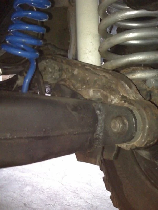
Once I was happy that I had trasfered the castor and the axle was square under the truck and I had the correct wheel base. I made a template of each mounting tap that was to be welded into place to attach the front end of the control arm to the axle. 8 tabs in all and each one was slightly diffrent so it would fit perfectly on the axle. As I went along I continued to check my measurments to see if the "pull" from welding moved anything. After I was done I just bolted the arms back on tight.
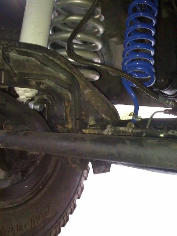
One headache was adjusting and remounting the ABS lines. I welded in new mounting tabs to bolt the abs harness to. On my truck the abs line ran on the outside of the DS. control arm. I was able just to use the same mounts and run it back onto the inside of the arm. The ridged brake lines needed to be move slightly, and with some carful manipulation I was able to make them work basically in the same place. The factory pan hard rod just got bolted into it factory mounts. It looks like I will be close to making some contact with the arm under extreme flexing situations. I will wait to see if I need to get one made with a larger bend over the arm untill testing is done. I am hoping it will work as is, then all I need to do is add Slees do it yourself adjustable panhard rod kit to adjust it back to center (3/8" is all it needs to be lengthed). The last problem is with the mounting location of the sway bar. I think If I did not extent the bar mounts at the frame down 2" I would not make any contact. I had to mount the tabs for the sway bar at the frame under the new arm location. This bug looks to be an easy one to fix.