
Disclaimer: this should work for any US spec 96 LX450 that has the factory installed RS3000 alarm, OTHER YEARS/MODELS MAY BE DIFFERENT, but this should still serve as a valuable guide. Do this mod at your own risk. Read through this guide and look at the pics before starting your install. I used the factory alarm harness to access many of the needed connections. You must make sure that you reconnect any wires which the RS3000 used as a starter interrupt. On the 96 LX, the RS3000 uses the Park/Neutral position switch signal, when the RS3000 harness is removed, just reconnect the two single wire connectors left dangling
Supplies
1 @ Viper 5701P (pink) 2-way/paging Remote start/alarm/keyless entry MSRP $499; $122 at Amazon (I purchased from gooddeals18, shipped within 2 days) EDIT: No longer available on Amazon, but it is on www.gooddeals18.com as a refurb for $92, limited qty.
1 @ Automotive relay: Radio Shack part # 275-226 $7
4 @ 1 amp general purpose diodes: Radio Shack, part #1N4001 or #1N4004 (I used 1N4004 since they were out of the other) $4
Toyota connectors and wire splices:
Misc supplies:
Phillips Screwdriver
10mm socket
14mm socket
Multi-meter
Solder
Soldering iron
Shrink wrap tubing
Assorted small zip ties
Split loom wire tubing, I used 3/8”
Quality electrical tape
Double sided foam tape
Crimp ring terminals
Crimp female flat blade terminals @ 4, to hook up to Radio Shack relay
Cheap wire striper/crimper
optional : appropriately sized T-Tap and Tap-In connectors or similar
Installation Instructions
Remove the front driver seat: 4 bolts (14mm socket) going into the floor, one at each corner, and disconnect one wire harness that goes to the seat bottom
*This allowed me to have access to the RS3000 (OEM alarm), and also made access under the dash much easier
Remove the dead pedal: one bolt (10mm socket) at the bottom, then it slides out
Remove the door sill/kick panel: remove one plastic trim fastener (flat blade screw driver) above the dead pedal area by unscrewing, then the rest of the trim piece will simply pop off
Disconnect the gas cap and hood release cables on the lower dash, just slide the cable to the side and out of the metal channel, then you have slack and can remove the cable end from the plastic pull
Remove the lower dash: 4 phillips screws
Remove the metal lower dash: 5 bolts (10mm socket)
Remove the air duct: 1 phillips screw, then it will just pull out.
Disconnect and remove the RS3000 (you can discard, put on fleabay, or on 'mud classifieds...), follow the harness to the kick panel area, and disconnect the three connectors, cut or remove the Led/glass breakage harness section, remove the theft deterrent harness . RECONNECT the two single wire connectors that are in the kick panel area, these are park/neutral wires, which the RS3000 used to interrupt the starter. Without this circuit being intact, you will not be able to start the engine.
Start the engine to verify that the starter is not interrupted, then turn off the engine
Decide where you want to mount the alarm module.
Before you mount it “permanently”, take cover off alarm module and move light flash fuse jumper to other position
Install the included valet switch. The switch is actually the status LED/Valet switch/antenna combined in one. I installed in the glove box as pictures, and then ran the wire behind the console to the alarm module. Plug the 3 connectors into the alarm module.
Install the siren in the engine bay (I just wedged mine into a hole in the inner fender, it has stayed put for now)
Thread siren wires, through the grommet (pictured) at the fire wall, and into the cabin, wire per spreadsheet
Save the large connector from the RS3000 harness that plugged in to the vehicle wiring (Kick Panel area), and 6”+ of the harness. Connect the wires from that connector to the Viper alarm wires as shown.
Wire the “Door Lock/Unlock” harness per spreadsheet, and plug in to alarm module.
Now the keyless entry should function
Install the hood switch into existing hole as pictured, and adjust the “depth” of switch
Thread gray hood switch wire (Viper “RS in” Harness), from under the dash, out to the engine bay using same grommet as siren wires, connect to hood switch. Wire the rest of the “RS in” wires per spreadsheet, and plug into alarm.
Viper has provided a Neutral Safety toggle switch (I can find no use in an auto trans 80 series), cut the harness about 6 “ long, and splice both wires together to complete the circuit, and shrink wrap. Plug in to alarm.
Create “T-Harness” with ignition switch connectors, wire per spread sheet. Note that some wires “tap in” while others are an interrupt type circuit, with different wires from the alarm harness connecting to each side of the original circuit. Any wires not in the spread sheet should be connected straight between the OEM connectors.
Connect the Automotive (Radio Shack) relay per spread sheet below, I mounted the relay to a module on the kick panel with double sided foam tape
Program the remote start/alarm/keyless entry, by using the Viper Installation Manual:
Final test alarm/keyless entry/remote start
Make it pretty with zip ties, electrical tape, plastic wire tubing... reassemble dash, kick panel, seat.


Supplies
1 @ Viper 5701P (pink) 2-way/paging Remote start/alarm/keyless entry MSRP $499; $122 at Amazon (I purchased from gooddeals18, shipped within 2 days) EDIT: No longer available on Amazon, but it is on www.gooddeals18.com as a refurb for $92, limited qty.
*You can spend an extra $120 if you want black key fobs instead, I didn’t care, as I am already secure in my manhood, besides my 80 is a Pink panty mobile. This is a good deal as it is the best Viper system available except it doesn't have a battery hungry LCD remote. This alarm comes with 2 fobs, one is a standard one way fob, the other is a two way LED remote/fob, that can tell you the status of the truck, cabin temp, etc
If you have a different brand or model of alarm/remote starter, you can probably still use most of the info here, just double check that the alarm harness wire functions go to the correct OEM/vehicle wires
If you have a different brand or model of alarm/remote starter, you can probably still use most of the info here, just double check that the alarm harness wire functions go to the correct OEM/vehicle wires
1 @ Automotive relay: Radio Shack part # 275-226 $7
4 @ 1 amp general purpose diodes: Radio Shack, part #1N4001 or #1N4004 (I used 1N4004 since they were out of the other) $4
Toyota connectors and wire splices:
90980-10873 HOUSING, CONNECTOR F $6.21 x1= $6.21
90980-10872 HOUSING, CONNECTOR M $7.62 x1= $7.62
82998-12370 TERMINAL, REPAIR W/W $4.67 x7= $32.69
82998-12330 TERMINAL, REPAIR W/W $4.67 x4= $18.68
82998-12380 TERMINAL, REPAIR W/W $4.67 x7= $32.69
82998-12340 TERMINAL, REPAIR W/W $4.67 x4= $18.68 About $115 total
OR get the ignition switch connector, and the connector and 6”+ wire harness that it plugs into, at a salvage yard
OR if your RS3000 already has a T harness, you can re use it
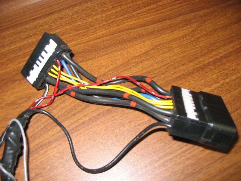
I got a T-harness, pictured below, from a Canadian ‘mudder, it was from the RS3000 in his 96 80 series, my 96 LX had an RS3000 from the factory and was wired per FSM, and had no T-harness. I took the T-harness as pictured below, and wired it per the spreadsheet. The picture below DOES NOT show the alarm harness wired/spliced in
Misc supplies:
Phillips Screwdriver
10mm socket
14mm socket
Multi-meter
Solder
Soldering iron
Shrink wrap tubing
Assorted small zip ties
Split loom wire tubing, I used 3/8”
Quality electrical tape
Double sided foam tape
Crimp ring terminals
Crimp female flat blade terminals @ 4, to hook up to Radio Shack relay
Cheap wire striper/crimper
optional : appropriately sized T-Tap and Tap-In connectors or similar
Installation Instructions
Remove the front driver seat: 4 bolts (14mm socket) going into the floor, one at each corner, and disconnect one wire harness that goes to the seat bottom
*This allowed me to have access to the RS3000 (OEM alarm), and also made access under the dash much easier
Remove the dead pedal: one bolt (10mm socket) at the bottom, then it slides out
Remove the door sill/kick panel: remove one plastic trim fastener (flat blade screw driver) above the dead pedal area by unscrewing, then the rest of the trim piece will simply pop off
Disconnect the gas cap and hood release cables on the lower dash, just slide the cable to the side and out of the metal channel, then you have slack and can remove the cable end from the plastic pull
Remove the lower dash: 4 phillips screws
Remove the metal lower dash: 5 bolts (10mm socket)
Remove the air duct: 1 phillips screw, then it will just pull out.
Disconnect and remove the RS3000 (you can discard, put on fleabay, or on 'mud classifieds...), follow the harness to the kick panel area, and disconnect the three connectors, cut or remove the Led/glass breakage harness section, remove the theft deterrent harness . RECONNECT the two single wire connectors that are in the kick panel area, these are park/neutral wires, which the RS3000 used to interrupt the starter. Without this circuit being intact, you will not be able to start the engine.
Start the engine to verify that the starter is not interrupted, then turn off the engine
Decide where you want to mount the alarm module.
*I decided to mount it to a module under the dash, it is about the same size and the alarm mounted easily and out of the way with some double sided foam tape. My considerations were that I am more concerned about keyless entry and remote starting and less concerned about theft. The location I choose might be easy for a thief to disarm/destroy the alarm. I also did not want to extend the run of the heavy gauge wiring, and could not find a better spot within reach of the provided wires.
Before you mount it “permanently”, take cover off alarm module and move light flash fuse jumper to other position
*Assuming yours is set from the factory the same as mine, if parking lights don’t blink with alarm/keyless entry, try switching this jumper back
Install the included valet switch. The switch is actually the status LED/Valet switch/antenna combined in one. I installed in the glove box as pictures, and then ran the wire behind the console to the alarm module. Plug the 3 connectors into the alarm module.
*I left the OEM led/glass breakage sensor dash piece and wires, as I thought that I might connect the LED to the Viper alarm some day
Install the siren in the engine bay (I just wedged mine into a hole in the inner fender, it has stayed put for now)
Thread siren wires, through the grommet (pictured) at the fire wall, and into the cabin, wire per spreadsheet
*Siren negative wire goes to chassis ground (I used OEM chassis ground at kick panel)
Save the large connector from the RS3000 harness that plugged in to the vehicle wiring (Kick Panel area), and 6”+ of the harness. Connect the wires from that connector to the Viper alarm wires as shown.
Diodes are like a one-way valve, so they will only work when spliced in in the correct direction. You will have to experiment with the direction. Both diodes on the door trigger wire go the same direction, and both diodes on the door lock/unlock go the other direction. See diagram below for how to use the diodes.
Once spliced, you can connect it to the vehicle harness and the alarm module. The alarm will basically function.Wire the “Door Lock/Unlock” harness per spreadsheet, and plug in to alarm module.
Now the keyless entry should function
Install the hood switch into existing hole as pictured, and adjust the “depth” of switch
Thread gray hood switch wire (Viper “RS in” Harness), from under the dash, out to the engine bay using same grommet as siren wires, connect to hood switch. Wire the rest of the “RS in” wires per spreadsheet, and plug into alarm.
Viper has provided a Neutral Safety toggle switch (I can find no use in an auto trans 80 series), cut the harness about 6 “ long, and splice both wires together to complete the circuit, and shrink wrap. Plug in to alarm.
Create “T-Harness” with ignition switch connectors, wire per spread sheet. Note that some wires “tap in” while others are an interrupt type circuit, with different wires from the alarm harness connecting to each side of the original circuit. Any wires not in the spread sheet should be connected straight between the OEM connectors.
Connect the Automotive (Radio Shack) relay per spread sheet below, I mounted the relay to a module on the kick panel with double sided foam tape
***IMPORTANT*** This relay is what gets you dome light supervision and MOST IMPORTANTLY, allows the Viper alarm to automatically shut down your headlights whenever the remote start shuts down or the alarm is armed. Without this, your battery is easily drained, accidentally. I will explain below:
If you usually leave your headlight switch in the on position, the 80 automatically shuts them down when you turn off the ignition and open the drivers door. If you remote start your car the lights will automatically turn on (if switch is in “on” position). If you let it automatically shut down (default 12 min), there is no one to open the door, and your lights will remain on. When you go out to your car a few hours later or the next morning, you will find your battery dead.
If you wire the relay, every time the remote start shuts off, or the alarm is armed, it will pulse the relay and in turn the dome light, the truck thinks you opened the driver door and turns off the headlights. The only “down” side, is that even when you manually turn off the ignition switch, it will send the pulse, so headlights now turn off with ignition and don’t wait for the driver to open the door. This also negates the OEM “retained power” feature which gave you the ability to roll windows up/down for about 20 seconds after ignition was turned off.
If you wire the relay, every time the remote start shuts off, or the alarm is armed, it will pulse the relay and in turn the dome light, the truck thinks you opened the driver door and turns off the headlights. The only “down” side, is that even when you manually turn off the ignition switch, it will send the pulse, so headlights now turn off with ignition and don’t wait for the driver to open the door. This also negates the OEM “retained power” feature which gave you the ability to roll windows up/down for about 20 seconds after ignition was turned off.
Program the remote start/alarm/keyless entry, by using the Viper Installation Manual:
YOU MUST CHANGE THE MENU 3, ITEM #1 TO AUTOMATIC TRANS (OPTION 2), the remote start will not function otherwise
The only other optional programming I have found that I wanted to change was:
Menu 3, menu item #3: changed to 0.8 seconds
Menu 3, menu item #5: changed to pulse count 2; this makes it so you have to push the remote start button twice, in order to activate the remote start function. This will help prevent accidental remote start activation.
Final test alarm/keyless entry/remote start
Make it pretty with zip ties, electrical tape, plastic wire tubing... reassemble dash, kick panel, seat.
Last edited:


