wiring wiper control on early fj45

This site may earn a commission from merchant affiliate
links, including eBay, Amazon, Skimlinks, and others.

Joined
Feb 24, 2009
Threads
50
Messages
83
Location
south australia
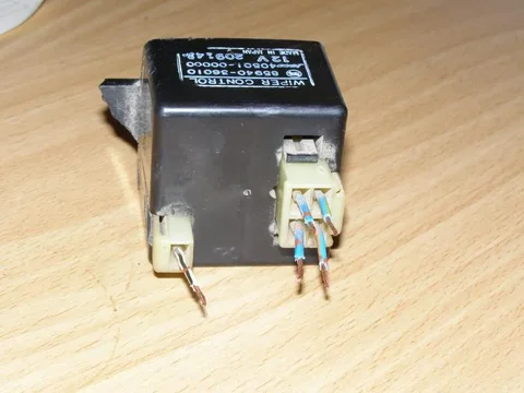
P6250096.webp hi guys just about to start driving my cruiser after doing a serious of mods and a new paint job and have one last problem ive fitted a 1981 roof window and doors now i have a problem with wipers the black box needs to be wired and i have later model switch has anyone done this and could help as its winter in oz and need wipers cheers shane:bang:
P6250096.webp
 
Can't help with this one much, but am very interested in this.

What year is the control box? Does it have any other function besides wiping? Like intermittent function?

Only thing I can contribute is the single WB wire is a ground wire if Toyota kept the same color codes for the trucks overseas. What are the other colors?

From what I can tell:

1 = LO (Blue with Orange stripe)
2= LY (Blue with Yellow stripe)
3 = LR (Blue with Red stripe)
4 = LW (Blue with White stripe
P6250096.webp
 
Last edited:
wipers

blue and red is other color its from a 1981 fj45 ute dont think intermittent but higher 3 or 4 speed just been told need to wire to get wipers running can anyone hav a look on there trucks?
 
I just looked at a FJ40 1981 schematic and a 1978 FJ55 schematic neither show this device. Both only show a switch with 6 wires 5 of which go straight to the wiper motor.

A 1988 FJ60 schematic does show a relay box that almost matches your box. So... I'm guessing that is a wiper relay box....

Anyone got an FJ45 schematic they can send me? :D
 
I'm 90% sure that box is an intermittent relay. If the switch you have is a four position switch it is 1-off, 2-intermittent, 3-low, 4-high. If it is an intermittent switch you are better off wiring everything stock. Toyota was on their own planet when it came to wiper circuit design.

Hate to say it, but hopefully all the components (switch, relay, wiper motor) came from the same donor rig, you'll need to spend quite a few hours and follow that wiring diagram.

Here is one I did for Jason's 45LV, using a late model FJ40 switch with intermittent position, a FJ60 intermittent box, and FJ60 wiper motor. You could do the same with a late model FJ40 wiper motor, you can bypass the relay for high low only without intermittent, the wiring diagrams show that. FJ60's and late model FJ40/5's shared the same circuitry.

If you're completely lost, detail exactly what components you're using, what they're from, and post detailed pictures of the wiring end of each showing wire colors and we'll try to help, but without that it's a total crapshoot. :confused:

And, I'd scratch the Early FJ45 label on this thread, because it has absolutely nothing to do with what you're attempting here. ;)
IMG_2084.webp
 
re fj45 wipers

ok heres the switch that came out of later 45 has a 6 plug with 1)yellow,2)blue/orange,3)black,4)blue,5)blue/black,6)blue/red then a 2 plug 1)blue/yellow 2)white/black how do i go wireing to wiper control box will try locate plugs as cut most of loom out of ute i wrecked :bang:
P6260097.webp
 
re fj45 wipers

ok guys i went out shed and dragges out loom i pulled the wiper wiring which has plugs both for switch and now need to know how to and where they wire up too i have worked out the 2 plug on switch would be for windscreen washer but now need to work out where wiper control wires to and wires to wiper motor thanks guys for help
P6270098.webp
 
re fj45 wiper install

ok ive tidyd the loom up its a 4 speed wiper switch has a 6 plug on switch then a 2 plug aswell and theres a 4 plug and single on wiper control box does anyone have a 81 fj45 wiper diagram or whole wiring diagram
P6270101.webp
 
re fj45 wipers

ok guys i stripped loom outa old wrekd truck and extended all wires now how do i hook it up does anyone have a wiring diagram :beer::bang:
P6270102.webp
 
Shane,

I couldn't find anything I had that was close. Hopefully this gives you a start. It is from a 82 FJ60 with intermittent. The wire colors on this may correspond with yours - after the plug, not on the switch itself (forgot about that twist). :rolleyes:

Anyhow, Remember:

Solid Blue is always power straight from the fuse. One will go to the switch and one goes directly to the motor for docking the wipers.

On the relay two of the wires are for the coil to pull in the relay, on mine it was blue and blue-yellow.

Wish I could be more help, but without it in front of me, I'm at a loss. :confused:
scan.webp
 
re wipers

could i just wire wipers with orig 3 speed switch not really fussed about intermittent wipers just need wipers
 
I posted this in my build but I wanted to also share it here as this post was one of the inspirations for adding intermittent wipers. Hopefully if someone else searches for this like i did the info will help. The info will be spread across a few posts. First the switch. A couple of things with it. We modified it to take an additional power (blue on the line diagram) to send power to the delay module. We also jumpered the black (ground for the washer motor) to the other ground on the switch and that ground goes to the main wiring harness ground. Could have ran two ground wires but this was easier.

-Geoff

20180915_162432.webp

20180915_162443.webp

20180915_162507.webp

20180915_162516.webp

20180915_155022.webp
 
Here's the line diagram for the wiper setup as well as the switch functions.

I had to make a couple of changes as noted to make the diagram match my switch wire colors.

I checked the continuity of each function and my switch operates exactly as shown.

When following my chickenscratch, please remember that I draw all of my plugs (both male and female) as if you are staring at the end of the plug. So when looking at the 6-prong main wiring harness (female) versus the 6-prong switch plug (male) you will note that they are mirrors and match up if you put them together like plugging them in. Don't know if this is the right way to draw them, but it's how I do it.

Also, note that the 4-prong switch wire positions do not line up with the delay module positions. Looking at it now I should have done that and may still change it yet, but as of today you need to make sure that the wire functions line up. For example, Blue on the switch plug does not line up with Blue on the delay module right now. The new sub harness matches it up by how we wired each end of the sub harness.

-Geoff

20180915_163554.webp

20180915_163603.webp

20180915_163608.webp

20180915_144421.webp

20180915_144402.webp
 
So on the line diagram note that what is called function "S" for the switch goes to "-S" on the delay module and then the output "S" on the delay module goes to "S" on the motor.

This is what the blue/white jumper wire is doing on the switch between the 4-prong plug and the 6-prong plug. It's taking the "S" delay module output and sending it through the main harness to the "S" on the wiper. Did it this way to prevent cutting the main wiring harness. Everything from the main wiring harness is unchanged. Everything changed is with the switch or sub harness only.

Photo of sub harness from switch to delay module. Again remember to follow the wiring diagram as how I currently have it wired, the sub harness does some crossovers on the wires.

-Geoff

20180915_165800.webp
 
@jgeoffr - are you able and interested in wiring up an early switch with an intermittent function?
 
Back
Top Bottom