The Alternator Regulator Voltage Booster Modification – Part 1 – Introduction (1 Viewer)

This site may earn a commission from merchant affiliate
links, including eBay, Amazon, Skimlinks, and others.

Joined
Apr 27, 2009
Threads
7
Messages
39
Location
Newcastle, Australia
This modification applies to most vehicle built before about 1990 (and quite a few after), but as I have a HJ60 I'm posting it here.

Vehicles built after 1990 have different electrical demands to older ones. They need less raw cranking power to start them, but must provide lots of ‘fill-in’ reserve power to ensure the proliferation of additional electrical devices fitted don’t suffer from ‘brown-out’ as different loads switch on and off. To accommodate these changed needs battery manufacturers and car makers have quietly made small alterations to battery chemistry and alternator regulator settings. Older vehicles will benefit from having their voltage regulator output better matched to the batteries available today, in particular they will achieve a longer battery life. (All figures quoted are @ 20°C)

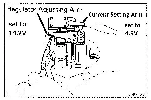
Old style Voltage Regulators use an electromagnet balanced against a spring to turn off/on power to the field coil in an alternator. Changing the spring tension or the contact spacing will change the voltage for the off/on balance point. Any auto electrician can easily adjust these regulators by carefully bending the arm that supports the regulating contacts (axial alignment and parallel surfaces must be maintained). 14.0V to 14.5V is what you need (depending on the type of battery fitted).
<Edit> Toyota currently specifies 14.5V +-0.6V, see here - http://www.autoshop101.com/forms/elec05.pdf <Edit>
voltage reg mech adjust.jpg
Electronic style Voltage Regulators are often sealed units with no internal adjustment possible. But they are easy to trick into regulating at a different voltage by changing the sense voltage that is input to them. The easiest way to increase an electronic Voltage Regulator’s output is to add a diode between the battery positive and the regulator sense input. This reduces the voltage sensed at the regulator by 0.6V, so the electronic Voltage Regulator will increase the output by the same amount in order to get its sense voltage back up to the ‘correct’ value. 13.8V + 0.6V = 14.4V. This is right at the correct charging level for modern batteries while remaining below the water loss voltage.

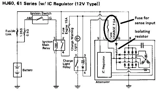
Most Electronic Voltage Regulators have 2 fuses, the ‘Charge’ or ‘Lamp’ fuse provides the sense voltage directly to the regulator while the ‘Engine’ fuse provides battery power to the Field Coil during and just after start-up when almost all of the alternator’s output is replentishing the battery. Note in the diagram below that the voltage from the ‘Engine’ fuse goes to the ‘IG’ input then through a diode and an ISOLATING resistor before joining the voltage from the ‘Charge’ fuse.

Check your vehicle’s electrical circuit diagram to see if your vehicle has separate fuses for the ‘IG’ and ‘L’ inputs and that there is an isolating resistor on the ‘IG’ input. The diode trick won’t work without the isolation.
charging system.jpg
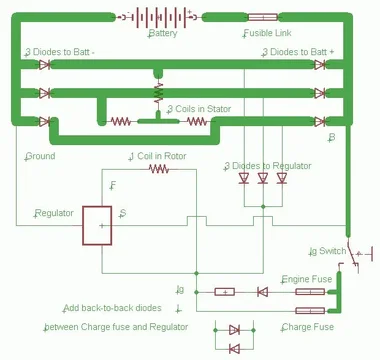
The Alternator Regulator Voltage Booster Modification is easy to apply to many older vehicles that have electronic regulators. In most vehicles the ‘Charge’ fuse for the alternator can be replaced with a diode/fuse combination (see diagram) to accomplish the modification without having to alter any wiring. This has the additional advantage of being able to be changed back at any time. You can buy this device on ebay for about $35 or build it yourself for less than $10.
alternator.jpg

See how to build it in part 2
voltage reg mech adjust.jpg
charging system.jpg
alternator.jpg
 
Last edited:
The Alternator Regulator Voltage Booster Modification – Part 2 – Doing It

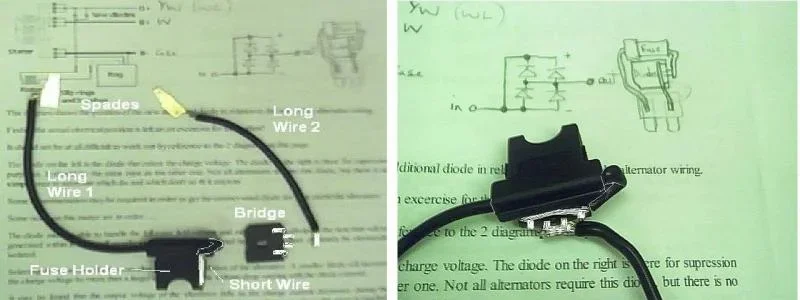
You only need a few parts to do it; diodes, a fuse holder, spades to plug into the ‘Charge’ fuse position and some wire. I bought a blade fuse holder which had a 300mm loop of cable attached ($2.95), an 8A Bridge Rectifier ($2.50) and cannibalized a broken relay for 2 off 4.8mm wide spade terminals (you may find it easier to solder onto the blades in a burnt out fuse).
alternator voltage booster1.jpg
Firstly I bent the legs on the Bridge Rectifier, the 2 AC ones to one side, the + & - to the other (the bridge provides 4 diodes in a single flat package – easier to handle and neater to use, the extra diodes parallel up to better share the load).

Next I cut the wire at about 35mm from the Fuse Holder, then cut the long side about in half. The shortest wire was stripped long enough to join to the + & - legs of the rectifier bridge, and long wire 2 was stripped long enough to reach the middle 2 x AC legs. The long ends were stripped about 5mm for the spades.
alternator voltage booster3.jpg alternator voltage booster4.jpg
Long wire 2 was soldered onto the middle 2 x AC legs of the diode bridge first, then the wire and bridge was wrapped in insulation tape. The short wire was soldered to the + & - legs of the bridge next and more tape used to secure it to the side of the fuse holder. Next the spades were soldered to the long wires. The spades were cleaned of flux and the wires bent to suitable shape.

I made a 1mm deep cut along the 12mm sides of a 3 x 6 x 12mm piece of plastic (Perspex) to use as a spacer/insulator. You can use wood, but I had the plastic ...

Parts, solder, tape, plastic and clean-up cost ~$6. Time to build was about 20 minutes, most of which was spent in getting out / putting away tools.

See Part 3 for how easy it is to fit
alternator voltage booster1.jpg
alternator voltage booster3.jpg
alternator voltage booster4.jpg
 
The Alternator Regulator Voltage Booster Modification – Part 3 – Fitting It

My 1988 Toyota Diesel Landcruiser had a low regulated output (~13.3V) to a maintenance-free starter battery that really needs ~14V to charge it properly. The battery’s built-in hydrometer (green=good, black=low, white=flat) has been black from the second week after it was fitted. Its second battery is a deep cycle hybrid type that will lose some water at 14V, but as it has vent caps I’ll be able to just keep replacing the lost water. The Redarc automatic disconnect between the batteries comes already set for the higher voltage.

I knew that I needed to match the Voltage Regulator to the Maintenance-Free battery’s charging requirements, so I did the research (summarised in part 4), checked out the suitability of applying the Alternator Regulator Voltage Booster Modification to the vehicle (as shown in part 1) and built the thing (part 2). That just left the easy part, fitting it.

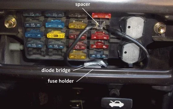
In my Landcruiser I took the cover off the fuse box, removed the ‘Charge’ fuse and plugged in the blades then the spacer. I then put the ‘Charge’ fuse into the Voltage Booster fuse holder, stuffed it into the dashboard space and put the cover back. 5 minutes after the engine was started the voltmeter settled at ~14V and everything worked as normal. And the hydrometer showed green after 100km of charging at the proper voltage. Yay !

alternator voltage booster5.jpg

I haven't had any significant water loss yet, so I guess I'm under the out gassing voltage for both batteries - ymmv ;). I'll edit this later if they do start using water.
alternator voltage booster5.jpg
 
Great write up, what style regulatot does the 24v hj61 come with, and is it worth while me doing this mod? Because when my spot lights and other accessories are running and my car is running my voltage drops off after a few minutes.. Is this a possible fix?
 
The Alternator Regulator Voltage Booster Modification – Part 4 - Technical Discussion

This information is in no particular order of importance, it’s just the accumulation of my research into why my maintenance–free battery never achieved a full charge.

Modern Voltage Regulators change their output voltage according to many factors such as accessory load, charge rate, battery condition and temperature. As such it is impossible to state exactly what voltage would be appropriate in any instance without stating all the conditions applying, so for this discussion please assume ‘final charging to recommended levels with low load and temperature at 20°C’.

Old style lead/acid batteries use a small amount of antimony to stiffen the soft lead plates. They show 6 x 2.1V = 12.6V when fully charged, and require a charging voltage of about 13.8V to overcome physical and chemical resistances. The antimony encourages hydrolysis so water has to be replaced regularly. Also the design of the lead plates allows high currents for a short period (starting), but will result in them dissolving largely away if a heavy load is applied for a long period (headlights left on). During re-charging the plates will re-form into lumps which will not provide the high currents ever again. It is almost impossible to buy these batteries anymore.

In the 1970s calcium was substituted for the antinomy to produce ‘maintenance-free’ batteries. This reduced the water losses, but increased the fully charged voltage to 6 x 2.25V = 13.5V. Charging voltages above 14.2V are required to achieve this. Hydrolysis will still occur if the charging voltage rises above 14.8V so accurate voltage regulation is very important. (Some maintenance-free batteries have a tiny amount of catalyst in the top of each cell that recombines any hydrogen gas given off with atmospheric oxygen back into water).

The plate design for lead/calcium grids allows for a deeper level of discharge without capacity loss, repeated moderate loads (like radiator cooling fans) can be better accommodated by this style of battery. The alloy also produces much higher resistance as the battery approaches full charge, so higher charging voltages can be used because the battery will self-limit the actual charge being accepted. Voltage Regulators are set at 14.2V to 14.5V. Most current vehicles use this type of battery.

<Edit> Apparently the chemistry has changed again, moving up another 0.3V, Toyota now recommend 14.5V +- 0.6V for proper charging, see - http://www.autoshop101.com/forms/elec05.pdf <Edit>
For older vehicles a hybrid style battery is available with one side of each cell stiffened with antinomy while the other uses calcium to provide a good compromise. The charged voltage is a little lower than for straight calcium as is the minimum voltage required to charge them fully (14.1V). They also exhibit high resistance as they approach fully charged, so 14.2V to 14.5V can be safely used with these too. This battery ‘replaces’ the straight antimony batteries of the past however the higher charging voltage requirement may need to be addressed.

To summarise: to charge pre 1990 batteries the voltage regulator was set to 13.3V – 13.8V, maintenance-free types need 14.0V – 14.5V and hybrids require 13.8V – 14.3V, or about 0.6V higher. Maximum charging voltage for all types above 14.8V will result in water loss. An old style voltage regulator set to 13.8V will still slowly charge maintenance-free and hybrid batteries ... eventually, but 14.0V to 14.3V will charge them properly and quickly.

So if you always drive older vehicles long distances between starts and your voltage regulator operates at the upper end of the range (13.8V) either type of battery will be fine.
If you commute more than 30 minutes each way each day you’ll (just) get by with a hybrid battery and your old voltage regulator.
For repeated short trips, or long storage times between uses, or just to upgrade and be done with worrying, get a maintenance-free calcium battery and change the voltage regulator to the modern 14.3V.

Changing the voltage regulator can be done in 3 ways – 1) get a new alternator with a modern regulator built in, 2) fit a new external regulator, 3) adjust the old voltage regulator. 1 can be expensive, but should be considered if either the existing alternator and/or regulator fail. 2 shouldn’t be too costly, but finding the ‘right’ replacement may be difficult. 3 takes a little knowledge and skill, but can be done quite cheaply.

Alternator Voltage Booster Modification Theory
An alternator’s output is controlled by applying a little power via a regulator circuit to the field coil inside the alternator. When the motor stops any unused power stored in the coil returns to the battery – a clear path for this back emf must be maintained, so most regulators are connected only to the ground return side of the field coil.

Typical alternators need about 4A to 5A in the field coil to produce 100A output, dropping proportionately as lower output is required. For safety any diode used to boost the output voltage should be able to handle around twice this amount – 8A. An 8A diode will drop about 0.72V at 4A, falling to about 0.6V at 0.1A. To allow any back emf to pass from the field coil to the battery an identical diode, mounted in the reverse direction, should be fitted (not needed with most Voltage Regulators, but cheap insurance in case).

Diode Bridges are 4 diodes in a single package. They are designed to convert alternating current to direct current, but can be used as inverse pairs of diodes when wired in different ways.
wiring diode bridges.jpg
A 6A or 8A diode bridge can be used for 12V or 24V alternators, use the 0.6V layout for 12V, or the 1.2V wiring for 24V.

More info about the modification here – SmartGauge Electronics - Increasing alternator charge voltages

If you are worried about such a large increase (0.6 / 13.8 = 4.5%) then you may want to use Schottky diodes that operate at lower voltages around 0.35V, giving 13.8V + 0.35V = 14.15V, but these diodes are much more costly.
wiring diode bridges.jpg
 
Last edited:
Maat,

If you have an electronic voltage regulator you'll need 2 (or 3) diodes in series forward and back to get the correct voltage. If its mechanical an auto electrician can do the adjustment easily.

Collect the relevant data first. 1) You need to know the battery type - Maintenance-free or hybrid. You need to know the system voltage when charged 2) at 2000 rpm and 3) at 'rest' (after standing with no load for 12 or more hours). Measure these with a proper digital multimeter at the battery terminals, don't rely on the gauge in the dashboard.

1) gives you the target voltage, 2) gives you your regulator's current setting and 3) tells you if you are achieving proper charging. See the technical discussion in Part 4.

If there is a difference between 1) and 2) work out how many diode drops (0.6V each) you need to get into the proper zone. Note - at 24V the power will be halved, so you'll get away with using diodes rated at 4A or more - this will save space.

bye.
 
Seems like an interesting mod. My aftermarket 120A alt puts out low voltage at idle, but gives the full 14.4V at 2K RPM. I'm wondering if this would solve my issue without causing an over voltage condition at full speed.
 
Interesting article, I'm going to have to rear it more thoroughly this evening.

FWIW Generous Motors, at least here in the States, uses a diode contained within a molding like either the mini-fuse (what ever it's designation is) or the ATC sized fuse. With one of those you can simply plug it into a fuse holder and have a diode in that circuit. Just watch the polarity, because it will go in either way.
I don't recall part numbers, but careful scrounging of a late model wreck or a visit to the dealer's parts counter should provide these parts. You also be able to get them from a real parts house (NAPA, etc.).
 
begennette,
My yellow top (D34/78) suggests 13.65-15 volts from the alternator. I would hate to screw up this nice battery. Are you suggesting that I will be killing it slowly if I do not make some form of upgrade here?

Thanks.

PS, I have a mm but am not sure where to measure the output from the alternator to check it.

Thanks.
 
Spook50,

Almost all alternators have low output below ~1000 rpm, your 14.4V is exactly right-on for charging modern batteries. :p

cruxarche,

See the reply to maat, you need to measure the battery terminal voltage after a run that is long enough to ensure a full charge (as full as your voltage regulator can manage). Don't stop the engine, get the multimeter onto the terminals, then use your third hand to rev the engine to about 2000 rpm. :D
You won't actually kill it, you'll just get a shorter life from oscillating between 95% - 80% - 95% charged rather than 100% - 90% - 100% charged

bye.
 
maat said:
Great write up, what style regulatot does the 24v hj61 come with, and is it worth while me doing this mod? Because when my spot lights and other accessories are running and my car is running my voltage drops off after a few minutes.. Is this a possible fix?

Maat,

I suspect you have an external mechanical voltage regulated, as I used to. They are easy to adjust, carefully, until you get the correct voltage, by bending the regulator tab up or down. This good idea/reminder for the voltage regulator is only applicable if you have a non adjustable electronic regulators. I purchased an adjustable electronic 24v regulator and it plugged straight into the existing wiring harness. I adjust the voltage with a small screwdriver. Easy.

Your question re voltage dropping off is more likely related to too much current draw, not the volts that current is being delivered at. Not wanting to highjack the OP thread, but try to figure out what watts or amps you are drawing. The 24v standard alternator was about 35A I think.

Tim

Sent from my iPad using IH8MUD
 
Update

It's been 3 weeks since I added 0.6V to my regulated voltage level, and the results are great. I went from charging at 13.3V to 13.9V.

The wipers work properly, no more too slooowww low speed and a good hi speed.
The lights appear unaffected, no huge extra brightness and no sudden failures from the extra voltage.
Starting appears to be easier (it's the middle of winter here in Australia).
The battery's built in hydrometer is finally showing green (fully charged).

All in all a good cheap modification.

bye.
 
Hi Tim, what is your 24v electronic regulator brand? I have looked around for one of these for a while.
Thanks.
Dmj

1987 VX 12H-T A440F
 
I know this thread is kind of old, but I thought it was better to recycle. I made my own diode pack for my 88 fj62 and plugged it in to the charge fuse slot and saw no effect on charge voltage. Charging starts at 13.7 when first started, then drops to 13.3 after idle comes down. At 2000 rpm it is also at 13.7. My initial thought was that my alternator used a split charge diode. But after fiddling around with it a bit, I discovered that with the charge fuse removed and nothing in its place I get the same voltage readings and no dash light. Am I wrong in assuming that I should get a charge warning light with nothing in the fuse slot? I'm wondering if the charge fuse wire has been tapped into elsewhere giving it voltage with or without the fuse plugged in? Any ideas?
 
Anybody?
 
EDIT: the rectifier bridge was broken and now having a new old stock alternator 20 Amp so test time. seems to charge with 14.4 Volts, but the other did that to.
also opened the voltage regulator and dit the FSM tests:
hj60.freeforums.org • View topic - 24V glow,alternator,dome,buzzer,battery, electrics


Bumping this because my 2 year old batteries are 91 amps but can be charged in house with 17 amps more.
So I have to check this fix and voltage is easily checked but amps are quite difficult.
I have tested my batteries with a load charger and seems fine, but still strange that after a trip the home charger can add 17 amps, that is 18% missing, or 82% amp charge
 
Last edited:

Users who are viewing this thread

Back
Top Bottom