

Speedometer and odometer not lighting up

This site may earn a commission from merchant affiliate
links, including eBay, Amazon, Skimlinks, and others.

Joined
Nov 26, 2020
Threads
8
Messages
40
Location
Vermont
1995 Toyota landcruiser

I checked all the fuses under the hood and steering wheel and they looked fine, dimmer is set all the way up, and I replaced the 4 bulbs that could've been lighting up these two sections, but nothing changed.

Also the head unit stopped working around the same time, not sure if they're related.
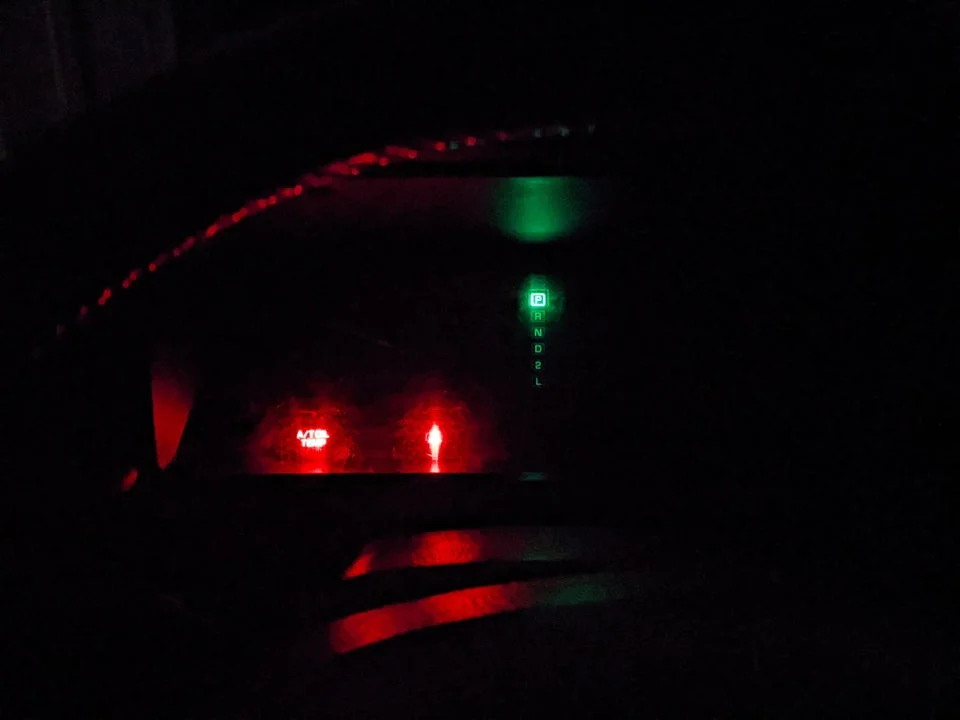
odo.webp
 
Break out the volt meter and see where you are getting voltage :)
 
Solid green wire should be +12 with the headlight switch ON. If no +12, check TAIL fuse.
White/black stripe is GROUND (left kick panel)
White/green stripe will be variable resistance to ground through the rheostat.

All schematic diagrams are available under the "resources" tab.
 
Solid green wire should be +12 with the headlight switch ON. If no +12, check TAIL fuse.
White/black stripe is GROUND (left kick panel)
White/green stripe will be variable resistance to ground through the rheostat.

All schematic diagrams are available under the "resources" tab.
Thanks for the information.

I changed the multimeter setting, it reads around 10 mV under the 2 setting, and 0 for the 20 setting, tail fuse is fine, and I checked all the fuses while I was at it, all pass a continuity test.
Would this mean I have a knick in my wire someplace?
 
Thanks for the information.

I changed the multimeter setting, it reads around 10 mV under the 2 setting, and 0 for the 20 setting, tail fuse is fine, and I checked all the fuses while I was at it, all pass a continuity test.
Would this mean I have a knick in my wire someplace?
Are you using a good ground for the meter? It's hard to tell in your pictures, but it looks all wrong to me.
There is a ground lug in the left kick panel, or use any bolt head that is screwed into the body.
 
I was using the ground from the cable, but just retested with ground set to a bolt, but I still got the same results.
 
Are you using a good ground for the meter? It's hard to tell in your pictures, but it looks all wrong to me.
There is a ground lug in the left kick panel, or use any bolt head that is screwed into the body.
I was just testing the dimmer knob to see if the resistance changes when I turn the knob, and it doesn't. I think this might be the issue, what do you think?
 
Can you make sure your meter is working by checking if you see 12 volts on a known hot wire or on the positive terminal of the battery? Then start tracing the wires back toward the battery.
 
Do you have an EWD (electrical wiring diagram)?
 
Last edited:
I don't know firsthand but have read that the dimmer controls the ground side of the circuit. If that's correct I assume you may not get voltage at the dimmer as you are testing but would get continuity between at least one of the dimmer socket wires and ground. Hopefully I'm not misleading you on this and I've not read the diagram(s) or tested the dimmer myself... EWD advice above is sure to help since you've checked the easy stuff. Also, if your stereo is aftermarket or if you have any other aftermarket wiring it's a more likely source for this type of issue than the factory wiring I'd guess.
 
I was just testing the dimmer knob to see if the resistance changes when I turn the knob, and it doesn't. I think this might be the issue, what do you think?
How were you testing it?
 
Can you make sure your meter is working by checking if you see 12 volts on a known hot wire or on the positive terminal of the battery? Then start tracing the wires back toward the battery.
So I did that, and got close to 12V, then tried the wires by the dimmer knob again, and was not really getting anything. Should I be following the solid green wire, which should be +12V, according to @jonheld's comment from earlier?
 
I don't know firsthand but have read that the dimmer controls the ground side of the circuit. If that's correct I assume you may not get voltage at the dimmer as you are testing but would get continuity between at least one of the dimmer socket wires and ground. Hopefully I'm not misleading you on this and I've not read the diagram(s) or tested the dimmer myself... EWD advice above is sure to help since you've checked the easy stuff. Also, if your stereo is aftermarket or if you have any other aftermarket wiring it's a more likely source for this type of issue than the factory wiring I'd guess.
I did a continuity test, and it passed for all 3 wires, I used bare metal on the frame as the ground, and then connected with each wire.

I also tried a continuity test with #2 on the top left. It looks like all 4 bulbs connect to this, and I did not get continuity. I feel like I should be getting continuity here.

PXL_20201127_195404516.webp
 
How were you testing it?

I changed the units on the multimeter, and I got values at the 100k ohms, so I think that is fine, it changes by 5k when I turn the knob all the way.

I also followed the cables from the dimmer knob to the cluster, and I have continuity between the solid green cable and the white/green cables.

I also tested the bulbs connected to 12V and ground, and they lit up, so I think what you're saying about the green cable needing 12V is the correct path.

So what should I do to fix the green cable not having 12V?
 
So what should I do to fix the green cable not having 12V?
I will repeat what I said in post #6. Schematic diagrams and FSMs are available under the "resources" tab. Download the EWD and the FSM. All of the information that you need to troubleshoot is in there. They also contain all the information about every single system in the vehicle and are invaluable to have.
 
I will repeat what I said in post #6. Schematic diagrams and FSMs are available under the "resources" tab. Download the EWD and the FSM. All of the information that you need to troubleshoot is in there. They also contain all the information about every single system in the vehicle and are invaluable to have.

Thanks! Found the wiring in the EWD.

Tail fuse and tail relay work fine. So it must be the wire connecting the tail fuse to the junction connector?

wiring.webp
 
Back
Top Bottom