

Ignitor and Coil question...

This site may earn a commission from merchant affiliate
links, including eBay, Amazon, Skimlinks, and others.

Joined
Mar 16, 2003
Threads
201
Messages
615
Ignitor and Coil question...followup question

I think I understand how things are suppose to be hooked up but wanted to run this by those with more experience...

Frame off renovation on a 2/79 FJ40. I'm getting ready to test run my engine before putting on the body. Everything in place with exception of any wire harnesses. Starter turns over when I apply power to the starter terminal. Now... I know I need to get power over to the fuel cut solenoid, and power to the coil to make things happen. I also see by the electrical diagram that the start circuit applies 12 volt to the coil, and the ignition circuit passes voltage to the coil after passing thru a resistor.

My questions revolve around where to "tap" for 12 volts on start, and then for the lower voltage after start, and how do I get these voltages to the coil. I'm concerned about burning out the coil or ruining the ignitor.

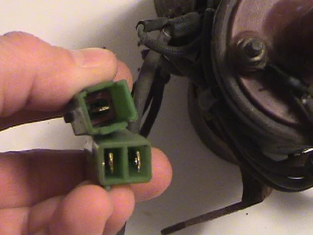
(1) Can anyone give me some insight as to what circuits the single and double blade connectors on the coil require and route to? (see picture) I know where the third connector with longer wire goes (my dizzy.)

(2) Any problem with directly applying 12volts to the fuel cut solenoid without going thru the emission computer I/O's.

I've almost got my head wrapped around this thing, but not quite. Any and all comments or insight would be appreciated.

Cheers, and Keep on Cruising!

Dave
Dsc00147.webp
Dsc00148.webp
 
Last edited:
one green plug is for the tach, the other is for the power to the coil.

Oddly I dont reall one of them having 2 male posts in it though?

I was thinking this is a 60....maybe its not?
 
Blue60 said:
My questions revolve around where to "tap" for 12 volts on start, and then for the lower voltage after start, and how do I get these voltages to the coil. I'm concerned about burning out the coil or ruining the ignitor.

(1) Can anyone give me some insight as to what circuits the single and double blade connectors on the coil require and route to? (see picture) I know where the third connector with longer wire goes (my dizzy.)

(2) Any problem with directly applying 12volts to the fuel cut solenoid without going thru the emission computer I/O's.

Dave

1) Generally, they go to a corresponding female plug end that you will find in the immediate vicinity of the male end. If you are lucky, there will only be one plug end in the vicinity. If you give more specific information about what vehicle, the year and the color codes of the wires we might be able to be more specific about what they do and where they go.

2) No. But again, why not just use the wire that is right there that is supposed to do the job?
 
If you are talking about a 79 FJ40....

The dual connector at the coil is 12V+ for the coil and 12V+ for the ignitor.
Ignition system grounds through the coil mount.
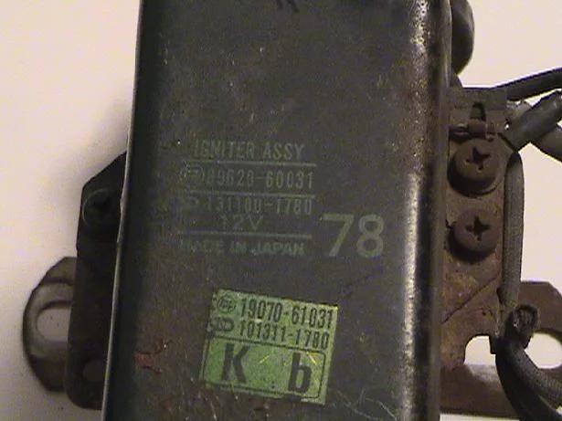
There is no ballast resistor on 78-newer trucks. That function is built into the ignitor.

The single connector at the coil is tach output for the emiss. computer and tachometer (not in USA cruisers).

The ICS receives straight 12V+ whenever the ignition is on. The other terminal is grounded by the emissions computer most of the time. For testing purposes you can just apply 12V+ to one terminal, and jumper the other terminal to any ground.

Blue60 said:
I think I understand how things are suppose to be hooked up but wanted to run this by those with more experience...

I'm getting ready to test run my engine before putting on the body. Everything in place with exception of any wire harnesses. Starter turns over when I apply power to the starter terminal. Now... I know I need to get power over to the fuel cut solenoid, and power to the coil to make things happen. I also see by the electrical diagram that the start circuit applies 12 volt to the coil, and the ignition circuit passes voltage to the coil after passing thru a resistor.

My questions revolve around where to "tap" for 12 volts on start, and then for the lower voltage after start, and how do I get these voltages to the coil. I'm concerned about burning out the coil or ruining the ignitor.

(1) Can anyone give me some insight as to what circuits the single and double blade connectors on the coil require and route to? (see picture) I know where the third connector with longer wire goes (my dizzy.)

(2) Any problem with directly applying 12volts to the fuel cut solenoid without going thru the emission computer I/O's.

I've almost got my head wrapped around this thing, but not quite. Any and all comments or insight would be appreciated.

Cheers, and Keep on Cruising!

Dave
 
Almost there...a followup question for Jim C.

Thanks to all who replied....

Pimp...the question concerns the original 2F setup that is in my 2/79 FJ40. Oddly enough, it is a later 2F engine manual (for my FJ60's) that shows that correct ICS (ignitor/coil system) setup, and shows how to do the few maintenance checks for voltage and resistance.

Pin...All my wire harnesses are out right now, otherwise it would make good sense to try and use complimentary connectors. I even considered laying out the front harness and using it to route power to various items as required. Might still do that later on.

JimC...BINGO! Precisely the information I was hoping to get to help me clarify my thoughts on how to proceed. Followup question for you though...

The two wires from the rear of the dual connector are colored. One is pink and one is white. My wiring diagram does not show this, though the engine manual does identify the colored wires and shows how to check the power transistor of the ICS by applying 1.5 volts to that connector.

When I put 12 volts to that dual connector does it matter which blade (which colored wire) of the connector I apply the 12 volts to and which one I ground? If so, which one and why? I plan on running a test lead from the battery positve pole straight to the correct dual connector blade...any problems with that?

I'll be ready to run the engine and leak check this beast as soon as I can get this fiqured out.


Thanks again for all the insight!

Cheers, and keep on Cruising!


Dave
 
Blue60 said:
JimC...BINGO! Precisely the information I was hoping to get to help me clarify my thoughts on how to proceed. Followup question for you though...
The two wires from the rear of the dual connector are colored. One is pink and one is white. My wiring diagram does not show this, though the engine manual does identify the colored wires and shows how to check the power transistor of the ICS by applying 1.5 volts to that connector.
"ICS" is Idle Cut Solenoid. It receives +12V and -12V power through the two pole connector at the carb.
When I put 12 volts to that dual connector does it matter which blade (which colored wire) of the connector I apply the 12 volts to and which one I ground? If so, which one and why? I plan on running a test lead from the battery positve pole straight to the correct dual connector blade...any problems with that?
I'll be ready to run the engine and leak check this beast as soon as I can get this fiqured out.
Dave
Now I think you are referring to the ignitor&coil. It receives +12V power to both poles of the dual connector. Remember that it must be grounded to the engine through the mounting bracket.
 
She's running...somewhat!

Jim C. you were right on with what I was trying to ask in a confused sort of way. Once I put 12 volts to both terminals of the duplex connector, I got good spark from the hi tension cord off the coil to the dizzy.

Ran the engine for about 10 minutes (first time in almost a year since I shut it down to start the frame up renovation), but had to keep playing with the choke and throttle to keep it running, even after warm up. But that's going to be another thread, after I do some reading!

Thanks for the help!

Cheers, and Keep on Cruising!

Dave
 
Back
Top Bottom