Navigation
Install the app
How to install the app on iOS
Follow along with the video below to see how to install our site as a web app on your home screen.
Note: This feature may not be available in some browsers.
More options
Style variation
You are using an out of date browser. It may not display this or other websites correctly.
You should upgrade or use an alternative browser.
You should upgrade or use an alternative browser.
Fuel Delivery Issues RTH
- Thread starter strictlyRUM
- Start date
This site may earn a commission from merchant affiliate
links, including eBay, Amazon, Skimlinks, and others.


- Thread starter
- #22
OK so it IS an amp issue. I got my DMM to read amps. I am getting 4.5 out of the battery and nothing out of the wires. Could this be a ground issue or is the battery just not charged enough. OR am I not reading the schematic correctly and there is a third connection needed for the ground to give up the amps? Sorry. Some engineering student I am huh?
- Thread starter
- #23
Not much help but, ignore the 'open loop' for the moment, it is referring to ECU status for fuelling during warm up.
regards
Dave
I have no idea on that?

The fuel pump motor has 2 connections.
Pin 3 of connector BO1 (red wire/green stripe) +12
Pin 5 of connector BO1 (white wire/black stripe) ground.
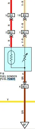
There are 3 additional connections on connector BO1 for the fuel level sender. Be certain of your wiring and that you're not using the brown ground wire for the sender.
If the pump runs with a 9 volt transistor radio battery, I have a hard time believing that it won't run off a car battery.
Pin 3 of connector BO1 (red wire/green stripe) +12
Pin 5 of connector BO1 (white wire/black stripe) ground.
There are 3 additional connections on connector BO1 for the fuel level sender. Be certain of your wiring and that you're not using the brown ground wire for the sender.
If the pump runs with a 9 volt transistor radio battery, I have a hard time believing that it won't run off a car battery.
Last edited:
I am not clear on the procedure you're using. You said the pump was removed from the tank. You said the pump ran when hooked up to a 9 volt battery, so we assume the pump is good.
Are you re-connecting the OEM harness to the pump or are you still using jumper wires?
Are you re-connecting the OEM harness to the pump or are you still using jumper wires?
- Thread starter
- #26
That is exactly where I am at. I just dont see what I am missing. Its got to be something stupid. Now that the charger has been on the battery for a while I am getting .05 amps at the jumper. I guess I will go back to school work for a while to see if I can get more power at the jumper. What is the BO1? I am on page 1199 for the testing process and it is telling me to use pots 6 and 5 for testing the pump. I did notice that if I follow the wires the 3 and 6 are what I want, but it will run with either 5,6 or 3,6 when hooked to the little battery. Is there somewhere upstream that I should check for an amp reading? I am at the connection by the door before it goes over the tank and up to the pump. No other grounds in the system that would affect the reading?
Thanks for your time guys
It is killing me it is almost done and I can figure out a stupid thing like this. That and I wont have any time but today and a week between spring and summer terms.
Jason
Thanks for your time guys
It is killing me it is almost done and I can figure out a stupid thing like this. That and I wont have any time but today and a week between spring and summer terms.
Jason
- Thread starter
- #27
I am not clear on the procedure you're using. You said the pump was removed from the tank. You said the pump ran when hooked up to a 9 volt battery, so we assume the pump is good.
Are you re-connecting the OEM harness to the pump or are you still using jumper wires?
Sorry, The pump is out on the floor of the cruiser. I disconnected the harness at the door where it goes through the floor. I am using jumpers from the harness to the pump and from a 9 volt battery to the pump. I do have a slight voltage drop from where the harness at the door attaches to the harness that goes over the tank and up to the pump so I have been trying to bypass that for now. I will run new wires for that later after I figure out what is going on.
Is that any clearer or not?
Jason

I have no idea on that?
When the engine is first started the ECU runs from a predetermined map, as it warms the ECU status changes and the ECU responds to inputs from the various sensors. The phrase 'open loop' has nothing to do with your pump wiring.
regards
Dave
Last edited:
- Thread starter
- #29
Ok Thanks. That is one less thing I have to worry about.
Connector BO1 is the FP/Fuel sender connection.That is exactly where I am at. I just dont see what I am missing. Its got to be something stupid. Now that the charger has been on the battery for a while I am getting .05 amps at the jumper. I guess I will go back to school work for a while to see if I can get more power at the jumper. What is the BO1? I am on page 1199 for the testing process and it is telling me to use pots 6 and 5 for testing the pump. I did notice that if I follow the wires the 3 and 6 are what I want, but it will run with either 5,6 or 3,6 when hooked to the little battery. Is there somewhere upstream that I should check for an amp reading? I am at the connection by the door before it goes over the tank and up to the pump. No other grounds in the system that would affect the reading?
Thanks for your time guys
It is killing me it is almost done and I can figure out a stupid thing like this. That and I wont have any time but today and a week between spring and summer terms.
Jason
My previous post was wrong. It is pins 3 and 5 on BO1. 3 is +12 (red/grn) and 5 is gnd (wht/blk).That is exactly where I am at. I just dont see what I am missing. Its got to be something stupid. Now that the charger has been on the battery for a while I am getting .05 amps at the jumper. I guess I will go back to school work for a while to see if I can get more power at the jumper. What is the BO1? I am on page 1199 for the testing process and it is telling me to use pots 6 and 5 for testing the pump. I did notice that if I follow the wires the 3 and 6 are what I want, but it will run with either 5,6 or 3,6 when hooked to the little battery. Is there somewhere upstream that I should check for an amp reading? I am at the connection by the door before it goes over the tank and up to the pump. No other grounds in the system that would affect the reading?
Thanks for your time guys
It is killing me it is almost done and I can figure out a stupid thing like this. That and I wont have any time but today and a week between spring and summer terms.
Jason
THis is the fuel sender circuit back to the gauge.