

Any electrical wizards out there?

This site may earn a commission from merchant affiliate
links, including eBay, Amazon, Skimlinks, and others.

Joined
Jul 30, 2003
Threads
50
Messages
253
Location
Maine
I've got a question about wiring. I'm at the end of putting a 13BT/H55f into my '78 fj40 but cannot get the wiring to work out. This is the first time I've done any of this so please be gentle...

I have a 24 volt starter, a 12 volt alternator and '78 fj40 electrical system.
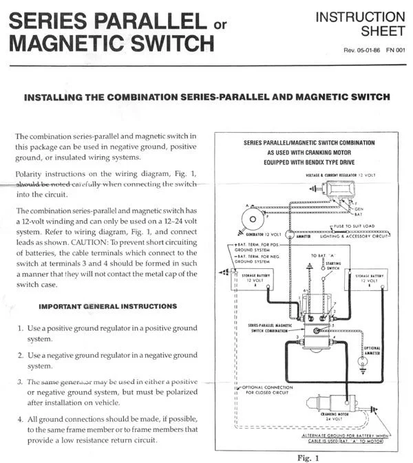
I also have a "Series Parallel or Magnetic Switch" that allows the 24v starter to get 24volts from 2 12volt batteries. I'll try to post a diagram that came with the switch.

I beleive I've hooked up all the thick lines using 1/0 cable.
When I test each batt, it is 12 volts. When I test thewire that goes from "1" to the ammeter in the diagram, it reads 12 volts.

The questions are;
1) where exactly should the lead from "7" on diagram go to?
2) How would this diagram be interpreted by someone more
wise about electrical diagrams?
3) On the cranking motor, the big fat gauge cable normally goes to positive or negative battery terminal?

4) This diagram shows an alternator with external regulator. My alt. has the internal reg.

5) the leads labeled as "F" "GEN" and "BAT" on this diagram are what in cruiser context symbols. My alt has 2 posts on top and a 3 wire pigtail. One post is "E" the other is "B"

6) I'm not sure about the polarity. This diagram is vague about witch battery terminals are positive versus negative. Any ideas?

7) Can anyone explain how the power travels between the ignition key, the alternator, and starter. What's the relationship? What "direction" does the current flow?

I've tried to figure this out myself but I'm at a wall and might start breaking tools I'll regret later..
Thanks a lot anyone who reads this.
SWITCH DIAGRAM-small.webp
 
Not a wizard...not done what your trying to do...but a 1/2 witted engineer that has designed and wired from ground zero two of my rolling wonders (and they still work w/no smoke or flames... 14 years for one of them). I'll give some initial thoughts/interpretations to your questions now and when I get my electrical bible in hand I'll hopefully get you the rest of the way home.

1) where exactly should the lead from "7" on diagram go to?

If your using your ign switch it goes to the post that gets 12v only when the ign switch is full clockwise (starting/cranking position). Another potential source is a seperate start botton on the dash.

2) How would this diagram be interpreted by someone more
wise about electrical diagrams?

When we find him...we'll ask. Anything specific to ask ?

3) On the cranking motor, the big fat gauge cable normally goes to positive or negative battery terminal?

For this question and others I am assuming you are maintaining a negative ground system. Therefore, the cranking motor will only have one "big fat" cable running to it and it does not come from the battery...it comes from the #4 post of the parallell magnetic switch. But this brings up another point. Make sure you have a big ass cable grounding your engine to frame and neg batt post to frame.

4) This diagram shows an alternator with external regulator. My alt. has the internal reg.

5) the leads labeled as "F" "GEN" and "BAT" on this diagram are what in cruiser context symbols. My alt has 2 posts on top and a 3 wire pigtail. One post is "E" the other is "B"


For these two questions...I'd feel more comfortable waiting till I consult my electrical bible at home tonight..so sit tight here.

6) I'm not sure about the polarity. This diagram is vague about witch battery terminals are positive versus negative. Any ideas?

Working on the assumption above (keeping it a negative ground system)...in the diagram the upper left posts as shown will be your negative posts. Lower right...positive.

7) Can anyone explain how the power travels between the ignition key, the alternator, and starter. What's the relationship? What "direction" does the current flow?

I should of had some ...ok many beers ...before doing this but I'll try to make some sense. Anyway, what is going on in this diagram is basically a 12 volt system, that, for the purpose of spinning the (24 volt) starter/cranking motor, needs to have another 12 volt battery wired in line/pressed into service. This is accomplished via the series-parallel magnetic switch combo gizmo. Your ignition and charging system should function for the most part as the did before. Although I do want to check a few things tonight. I'll show my age here and I'll use ford as an example cause it comes to mind. For many years Fords used a separate starter soleniod (mounted on the fender wall, not sitting on top of the starter) to supply the power to the starter. Try to think of the series-parallel magnetic switch in the same fashion with only one twist. It also has the function of tieing in your second 12 volt battery to the system in order to provide 24 volts to the starter/cranking motor.

Hope this helps some for now.
 
On the way home I thought about it some more...more simply stated...

I don't believe you have to do anything different with the wiring of your alt w/internal regulator. Wire it back in as it was. In it's simplest terms the only thing you are doing is changing from a starter with piggy backed solenoid switch (12 volt variety) to a stand alone starter (24 volt) with fender or firewall mounted solenoid switch (on steroids in this case).

The 12v ign switch wire that you need to wire into post 7 on the series-parallel solenoid switch is the black/white wire that formerly ran to the "piggy backed" solenoid of your old starter. It's the wire on the terminal next to the big ass lug wired to the starter.

Other than that you need to run a ground to lug 6 on the series-parallel solenoid switch.

Last is running the big cable as shown from the batts, to the series-parallel solenoid switch, to the starter.

Yuo don't need to worry about "the optional ammeter wiring" or the "optional connection for closed circut" wiring.

Hope I didn't confuse this for you....
 
Toddslater,

Thanks for your replies, they make sense but for some reason, only while reading, doh.
I went to the local battery world and they explained to me but still, I now have 12 volts at the "AM" wire on the ignition switch at the column. This is with the key in the off position (or no key at all.)
When I turn the key to the next position, my meter reads 6volts at the "AM" and 6 volts at "ACC" wire. If I turn the key to the next position, the meter shows 0 volts at all 4 wires (AM, ACC, ST, IG)!

So, power is going from the "Battery A" positive to the switch, but seems to quit there...Any ideas? Is this doomed?

Thanks again.
 
Just on a perchance that you may have run an extra wire where it need not have been done...in the diagram above wherein it is shown (bottom to top), terminal post 7, starting switch, to BAT "A". You haven't run any separate wire to BAT "A" there have you ? If yes, remove it. remember the wire you need to connect to post 7 is the wire that is black and white that used to connect to your starter solenoid (tells it it's show time and recieves it's 12v via the ign switch when turned to the start position).

If you didn't run the additional wire and your hooked in as I've said...hmmm then we'll need to look elsewhere. If so, tell me excactly what you done with your ign switch wiring (hopefully nothing), other wires in existence from the stock harness, and which wires/cable you've run from the above diagram.
 
The relay is basically a high current DPDT switch. The Positive side of the batteries is on the right. The wire that goes to terminal 1 is the large white wire with blue stripe that used to go to the battery + lug through the fusible link. Terminal 7 goes to the "start" position of the ignition switch (the small wire that used to go to the starter solenoid lug and not to the coil). It sounds like your ignition switch isn't working. You could just bypass it with a momentary push button switch.
 
Okay, that makes sense...I'll have to try again tommorrow when it's not 31 degrees out.
Thank you guys for your advice. I am thinking maybe the existing wiring wasn't exactly "stock" (I am not the oroginal owner.) I can say that it seemd to all work fine for the time I've been driving it. There were some issues like the cooling fan and lighter never worked but bench tested okay. It looks mostly like the factory diagrams but they are vague to me so I could easily misread them. I have the batteries hooked up the way the diagram shows with the positive terms on the right.
some questions:

1)Should the current flow from terminal 1 towards the fuse block? I've got one end where the fusable link is going to terminal 1 but I'm not sure where the other end should be going??

2)Should the terminal "AM" on the starter switch always read 12 volts?

3) Should I just rewire the whole thing?

I've also noticed my skin breaks more easily in the cold season....

Thanks again
 
Hmmm, I think I've got it like that now. Somehow, I'm getting voltage on the top most fuses, but the black w/ yellow striped wires and fuses get no voltage...Still, no lights or acessories work, even though there is 12v going to them...Aaaargh.
 
Hmmm, let's run thru this wire by wire from your original set up...as I understand it, it was working fine except for the lighter and cooling fan,

On the diagram above, lets make the battery on the left your original battery as wired into your original system. Originally, the positive post had wired on to it (at a minimum) one large cable that went directly to the starter and also at least one 10 gauge wire that dissappeared into the wiring harness.


First wire to relocate:

The cable that formerly went directly to the starter, should now be connected to the series-parallel switch terminal post 1.

The 10 gauge wire (and any other wire that was there before) that was also part of your original setup, should be just as it was tied into the battery + terminal connector.

In other words only the cable coming from the batt + post that was formerly hooked up to the starter, needs to be relocated from what your original set up was.

****Important, there is no need to run any additional wire from series-parallel switch terminal post 1 back to the ammeter and likewise no need to run an additional wire from the ammeter to the lighting and accessory circuit.****(this is what the 10 gauge wire from your original set up did, does , and should contiue to do).****

Second wire to relocate:

There was a black and white wire that used to go to your old starter solenoid switch. This is the wire that used to trigger the selonoid, now it needs to be relocated to the series-parallel switch terminal post number 7.

>>>At this point all of your stock wires that were part of your original set up have been accounted for and found their new homes.<<<<


Now it's time to plop in the second AC/Delco of your choice and finish up the wiring...also at this point you are done with any wires and wiring from your original harness....this from here on out is all new wire and/or cable.

After you've installed and secured your new battery in it's final resting place...

First new wire to add:

Install a black cable from the battery negative post to series-parallel switch post (here is where the figure is tough for me too see the number correctly) I think it's 3, but it is the lug just to the right of terminal 7 shown on the figure above.

Second new wire to install:

Install red cable from second battery + post to series-parallel switch terminal post 2. Located below terminal post 1 in the above figure.

Third new wire to install:

Install a red cable from series-parallel switch terminal post 4 to the post on top of your new 24volt desiel starter motor.

Fourth new wire to install:

Install a black cable (or possibley a 10 gauge wire, if the terminal post 6 is small and not accepting of a large lug connector) from series-parallel switch terminal post 6 to a cleaned location on the firewall or fender wall (where ever you have mounted your series-parallel switch.

Lastly, check to make sure you have a nice ground cable attached somewhere on your engine block to a nice clean location on the frame.


That is all the wiring you should need to do. Wires you do not need to run are as follows in addition to the ones mentioned above in the ****important****section:

The wire from series-parallel switch terminal post 5 shown above going to an "optional" ammeter....not neceassary

The "optional connection for closed circuit" wire shown above running from the batt A to starter....not necessary

Hopefully this will get you there and all we'll need to do is get your lighter and cooling fan going.

Where are you in Maine, my brother lives in Newry...don't think he would be able to help but I think he knows someone that could eyeball it .
 
Wow! Okay, I'm going to try this setup out this evening after work. I like the sound of this approach. Thank you so much again for helping out. Part of my issue is I did not label the wire that used to go to my old starter solenoid. I have a few that might be it, but don't know definitley which one...I guess that I could find out once the other wiring is completed. What do you refer to by second AC/Delco? The second battery? Also, the truck originally was not wired into the ammeter on the gauge console?! Should it be? I would like it to be, but not if it complicates this even more. Doh, this makes me feel like an idiot...
I live in the Portland area, I think it's like 45-60 minutes (just a guess) from Newry.
 
Didn't label the starter solenoid wire eh ??? Well, Of the few that might be it hopefully one of them is black and white in color and dangling down in the area of the former starter. One way ensure you get the right wire is with your volt meter and a friend. With your volt meter in DC mode and your friend working the ign switch. Check you "potential" former starter solenoid wires to see which one gets 12volts "only when the ign is turned to the start position".

Sorry about the second AC/Delco thing ...that is indeed the reference I was making to hooking up your second battery.

Regarding the ammeter gauge console issue. Well, it was wired in at the factory when it left and I don't see why someone would go to the trouble of disconnecting the ammeter from the system. Unless someone at some point put some aftermarket gauges in. None the less, at this point lets leave that one alone until we get your truck up and going. Then we can tackle the lighter, coolinfg fan, and if the ammeter doesn't come back to life...we get it too.

My brother is headed back to Newry today...we did an early turkey day as he gets real busy when the snow starts flyin. Sounds right...an hour down to Portland.
 
Ahhh, okay, I may have found the correct wire then...we'll see. The cooling fan has been retired, will that screw up the electrical system? It never came on before and I never came close to overheating, so, to gain space I took it out. Should the multimeter get it's ground from something not attached to the vehicle? I tried grounding it to the chassis and also tried using the neg battery post as ground (which I think was not correct.) I get alsomst the same readings either way, but when it's ground to the neg. batt. post it gets higher voltage readings like 12.xx versus 9.xx-11.xx. Where are you located, N.E. I'm guessing?
Well, thanks again, I'll be back, lol.
 
Taking the electric cooling fan off line shouldn't mean anything. I can understand why it never came on...living in Portland, ME. On my 89 w/ac it's gotta be smokin hot for it to come on. As far as the multi meter...it must be grounded somewhere on the vehicle. The neg post is great if it's in reach...if not a good shiny piece of the body/chassis, a non rusty bolt, or the like is best. Grounding issues with the multi meter might explain some of the rather erratic readings you've had in the past.

I am located 40 mi. SW of Philly, in Avondale, PA.
 
"First wire to relocate:

The cable that formerly went directly to the starter, should now be connected to the series-parallel switch terminal post 1."

-Do you mean formerly went to the starting motor or the ignition cylinder "ST" black wire w/ white stripe?

"Install a black cable from the battery negative post to series-parallel switch post (here is where the figure is tough for me too see the number correctly) I think it's 3, but it is the lug just to the right of terminal 7 shown on the figure above."

-FYI, it is number 2. Sorry it's not a better scan.


"Second wire to relocate:

There was a black and white wire that used to go to your old starter solenoid switch...."

-In this statement, is the "old starter solenoid switch" the starter switch on the steering column? If so
should it have been going directly to the old starter?
__________________________________________________________________________________-

I've got the second battery wired as you and the diagram instruct. Now I'm still a bit fuzzy on what existing wire gets attached to post #1. If I understand it, the WL wire with the fusable link should go from post #1 through the firewall to the fuse block, (b+) on the alternator, and whereever else it used to go? In the end, I should only have one 1/0 gauge wire and one smaller wire connected to post #1? The smaller one feeds the fuse block, the other 1/0 cable goes to the 24v starter motor?

Thanks again, getting closer, and still feel like an idiot. ;)
 
""First wire to relocate:

The cable that formerly went directly to the starter, should now be connected to the series-parallel switch terminal post 1."

-Do you mean formerly went to the starting motor or the ignition cylinder "ST" black wire w/ white stripe?"

>>>>No, I mean the thick cable that goes from the + terminal in your original battery down to the lug on the starter. I am definitly not talking about any little 12/14 gauge wire here.<<<<<<

""Second wire to relocate:

There was a black and white wire that used to go to your old starter solenoid switch...."

-In this statement, is the "old starter solenoid switch" the starter switch on the steering column? If so
should it have been going directly to the old starter? "

>>>>>There really is/was/should be no need for you to be futzing with the switch on the steering column.....unless I am too late and you already have. This statement refers to the 12/14 gauge wire that was on a push on terminal spade connector on the starter solenoid. I'm charging the digi now so as to make this very visible to you.<<<<<


"........ Now I'm still a bit fuzzy on what existing wire gets attached to post #1. If I understand it, the WL wire with the fusable link should go from post #1 through the firewall to the fuse block, (b+) on the alternator, and whereever else it used to go? In the end, I should only have one 1/0 gauge wire and one smaller wire connected to post #1? The smaller one feeds the fuse block, the other 1/0 cable goes to the 24v starter motor?"

>>>> Yes and no on the above. Remember the digi is warming up so it may ultimately help...till then here goes. In your original configuration you would have had emanating from your + battery terminal post one large cable connected there and running to the lug on the starter mentioned above... and another 10 gauge (maybe a little larger) wire with fuseable link that dissappeared into the wiring harness (and yes it does eventually end up powering the fuse block). Now...what I am saying is there is no need to relocate this 10 gauge fuseable link wire down to post #1 on the series-parallel switch as shown on the drawing....and/or and more importantly, I certainly do not want you to run an "additional" 10 gauge wire from terimnal post #1 as shown on the diagram through the firewall,to the fuse block, anywhere near the B+ on the alternator or wherever else it used to go. No how, no way...if you just leave that wire where it was originally connected to the +post of the battery you will be fine. <<<<<
 
">>>>>There really is/was/should be no need for you to be futzing with the switch on the steering column.....unless I am too late and you already have. This statement refers to the 12/14 gauge wire that was on a push on terminal spade connector on the starter solenoid. I'm charging the digi now so as to make this very visible to you.<<<<<"

No worries, I was just taking reading there with the multi meter
Thanks so much for this help and the pictures that may appear. Can't wait to get my cruiser running and stop taking the bus! Thank you
 
Okay here is the first pic.

Shown is what your original starter set up should look like. In pic is the starter motor and the sloenois (piggy backed on top of the starter).

The big red cable attached here is the one that needs to be attached to series-parellel post #1. The other end of this big red cable is attched to the + post of the battery....shown in next photo.

The other skinny wire you see attached to the soleniod (looks black in photo but is actually black and white stripe in person) is the wire that needs to be relocated to post #7 on the series-parallel switch. And as I mentioned previously it only sees 12volts when the ign key is twisted to the start position.

Two wires two relocations.
 
Yes, I do know where that small wire is now! Thank you for the picture, too
:)
 
Next pic is a pull back shot. We hopefully got a firm grip on the starter wire relocations....now we will peek at the (hopefully last) wire that seems to be giving you problems....the 10 gauge fuseable link wire that ultimately feeds the fuse block.

In the photo you will see attached to my + battery post a total of 3 wires (2 large cable and 1 @ 10gauge fuseable link). The first wire/cable from the lower left is a thick black cable....never mind this cable as it goes directly to my winch.

Next in the connection line is the @10gauge fuseable link that ultimately goes to feed the fuse block. What I am saying is you should just go ahead and keep the wire in this location. The drawing you have merely shows it schematically attached to post #1 of the series-parallel switch. I am saying there is no need to relocate this 10 gauge fuseable link wire to that location. Keep it where it was originally. And by "no means" add a wire (a duplicative wire) to post #1 on the series-parallel switch and run it back as shown on the drawing.

The last wire/cable is the big red cable that runs from the + batt terminal down to the starter.....this is the one that we now should have attached to post #1 of the series parallel switch.
 
Back
Top Bottom